Audio level meter

Active Publication Date: 2009-11-19
INTERDIGITAL CE PATENT HLDG
View PDF4 Cites 1 Cited by
  • Summary
  • Abstract
  • Description
  • Claims
  • Application Information

AI Technical Summary

Problems solved by technology

Various types of audio level meters exist, like e.g., the VU (Volume Unit) Meter and the Peak Program Meter, whose readings differ for the same input signal and are not easy to compare with each other.
On the other hand, it shall also indicate the headroom that is still left before the system goes into saturation as this would cause audible distortions.

Method used


Image

  • Audio level meter
  • Audio level meter
  • Audio level meter

Examples


Embodiment Construction

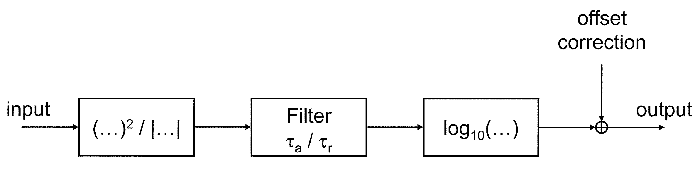
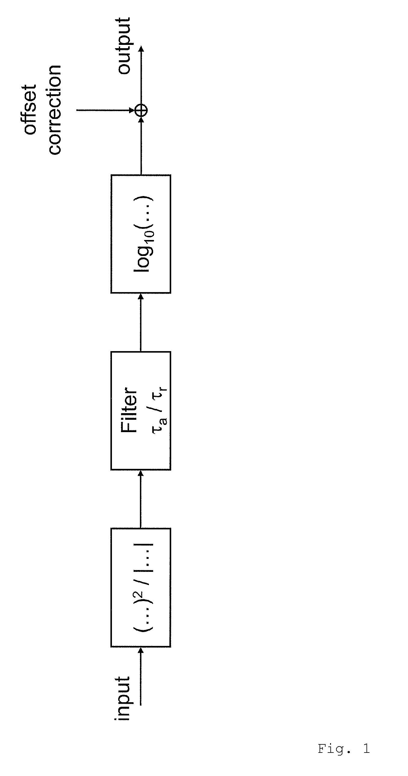
[0004]The invention is based upon the finding that, for a sinusoidal input signal, the difference between the true signal power and the reading of an audio level meter substantially only depends from three variables: The treatment of the input signal, i.e. determining the absolute value or squaring the input signal, the attack time of a lowpass filter used in the audio level meter and the release time of that filter.

[0005]In a corresponding equation phi_0 is the phase angle, for which the rising and decaying portions of a signal under test are equal.

[0006]In the case of a squared input signal, phi_0 is determined according to the following equation:

(b−a)*sin(2*phi—0)−2*(b−a)*phi—0*cos(2*phi—0)−a*pi*cos(2*phi—0)=0

[0007]In the case of the absolute value of the input signal being determined, phi_0 is determined according to the following equation:

(a−b)*phi—0*sin(phi_0)+(a−b)*cos(phi—0)+b−a*pi / 2*sin(phi—0)=0

wherein a=1−exp(−1 / (τa·fs)), b=1−exp(1 / (τr·fs)) and fs is the sampling frequency...


PUM


Abstract

A circuit for correcting the output of an audio level meter comprises input means for generating the square or the absolute value of an input signal, a low pass filter having a predetermined attack time and release time, and output means for converting the output signal from a linear scale to a logarithmic scale. The circuit further comprises a correction means to which an information about whether the input signal to the audio level meter was subject to squaring or converting into an absolute value at the input, as well as the attack and release time of the low pass filter, are supplied as input values, and which provides, at its output, a value representing the difference between the output of the audio level meter and the true signal power of the input signal.

Description

[0001]Fixed correction terms for detectors using input filters having fixed attack / release times or other detector types are commonly used in AC voltage measurement equipment like Multimeters or audio measurement systems like “Audio Precision”.[0002]Various types of audio level meters exist, like e.g., the VU (Volume Unit) Meter and the Peak Program Meter, whose readings differ for the same input signal and are not easy to compare with each other. This is due to the fact that an audio level meter shall serve two conflicting purposes. On the one hand, it shall indicate the perceived loudness of an audio signal, which is related to the signal power. On the other hand, it shall also indicate the headroom that is still left before the system goes into saturation as this would cause audible distortions. In this regard, further distinguishing is needed between an analog and a digital system. An analog system overloads relatively gradually whereas a digital one overloads abruptly. Therefor...

Claims


Application Information

Patent Timeline
IPC IPC(8): G06F17/00
CPCH04R29/00H04R29/008G01R19/04G01R19/02H04S7/40
Inventor SCHLOSSER, MARKUSSCHREIBER, ULRICHSIECK, MARIO
Owner INTERDIGITAL CE PATENT HLDG
Why Eureka
Try Eureka