
Automated discovery of devices in large utility monitoring systems

a utility monitoring and automatic discovery technology, applied in the direction of electric devices, instruments, transportation and packaging, etc., can solve the problems of network congestion becoming a more significant problem, the auto-discovery process is extremely slow, and the response time is limited, so as to reduce the number of packets, improve the efficiency of the auto-discovery process, and fine-tune each devi

Inactive Publication Date: 2009-11-19
SQUARE D CO
View PDF15 Cites 27 Cited by
  • Summary
  • Abstract
  • Description
  • Claims
  • Application Information

AI Technical Summary

Benefits of technology

"The patent describes an algorithm that can automatically identify and analyze data from a central computer system and make decisions based on that data. The algorithm can interpret data from electrical nodes and determine their response time, type of response, and identities. It can also compare the data against a lookup table and adjust its search priority based on statistical probabilities. This algorithm significantly increases the efficiency of identifying and analyzing devices in a utility monitoring system, especially large ones with many nodes and devices."

Problems solved by technology

However, due to the nature of certain utility monitoring systems, a number of factors can cause the auto-discovery process to be extremely slow.
Although the serial communications protocol may eventually communicate data over a faster one, such as Ethernet, response times are limited by the most restrictive communications pipe in the utility monitoring system.
Moreover, the larger the utility monitoring system (e.g., over 1000 nodes or devices and over 200 unique IP addresses), network congestion becomes a more significant problem.
If it takes 24 hours or even longer to auto-learn the identities of devices present in the utility monitoring system, such a delay may be considered unacceptable and potentially unsafe.
As devices are added or removed, the central computer system must quickly be able to learn new device identities and discard old ones, otherwise efficiency is lost.

Method used


Image

  • Automated discovery of devices in large utility monitoring systems
  • Automated discovery of devices in large utility monitoring systems
  • Automated discovery of devices in large utility monitoring systems

Examples


Embodiment Construction

[0017]Although the invention will be described in connection with certain preferred embodiments, it will be understood that the invention is not limited to those particular embodiments. On the contrary, the invention is intended to include all alternatives, modifications and equivalent arrangements as may be included within the spirit and scope of the invention as defined by the appended claims.

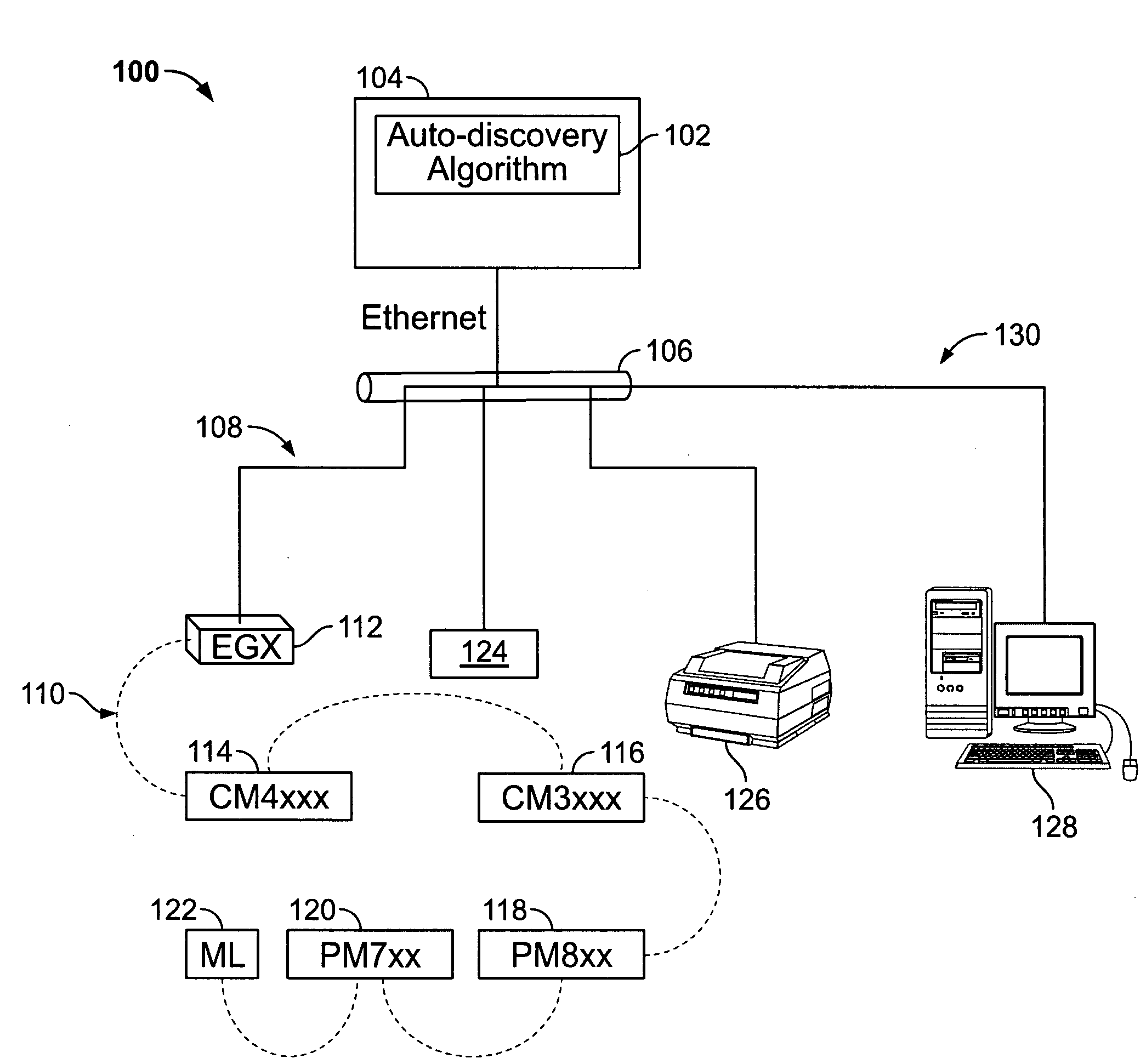
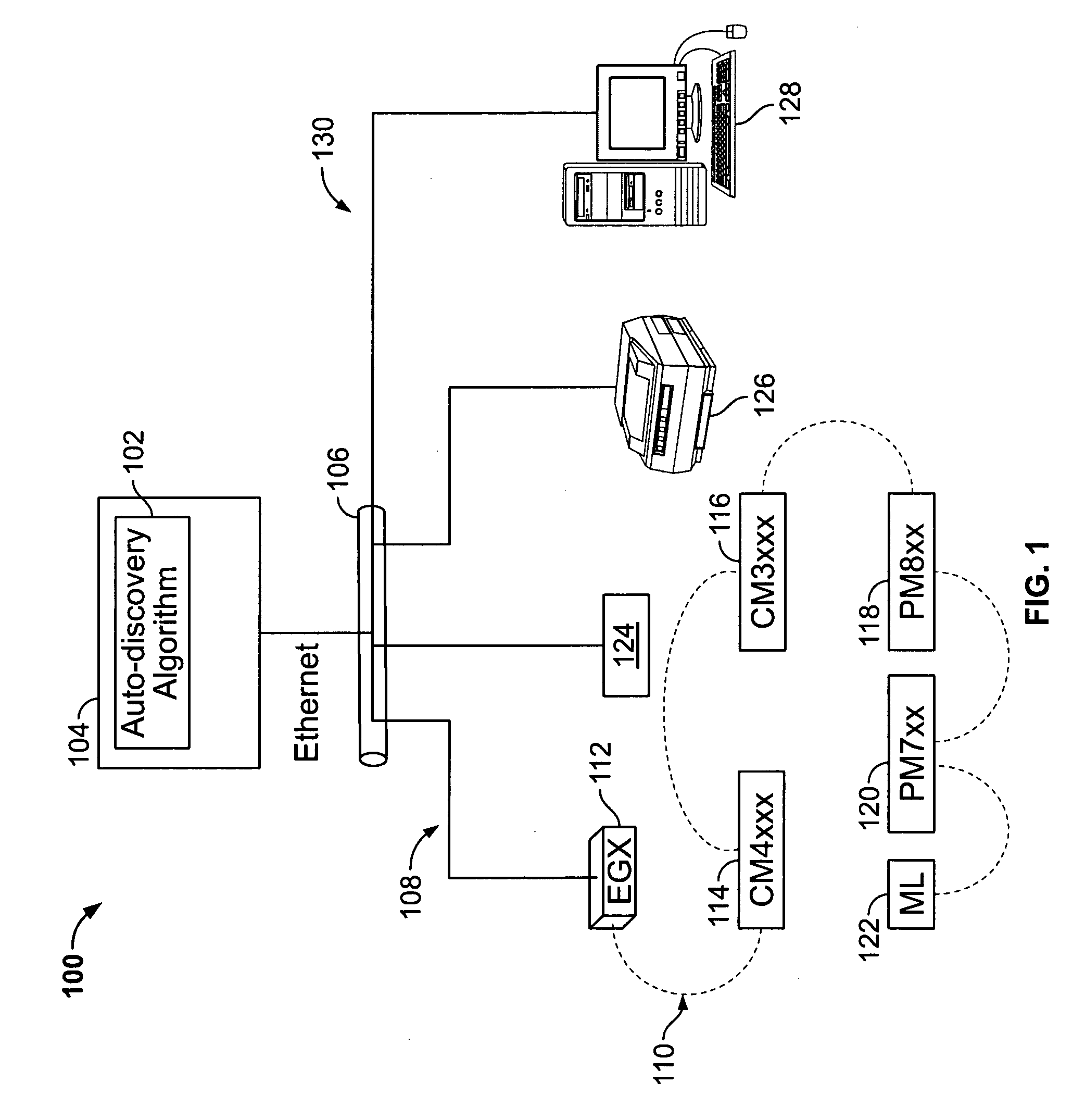
[0018]Referring now to the drawings, and initially to FIG. 1, an exemplary utility monitoring system 100 is shown. The monitoring system 100 may be any system that monitors measurable characteristics of a utility. The utility being monitored in the monitoring system 100 can be any of the five utilities designated by the acronym WAGES, or water, air, gas, electricity, or steam. In the illustrated example shown in FIG. 1, the utility is electricity, though aspects disclosed herein apply equally to any of the other four utilities. The utility monitoring system 100 is typically arranged in a hier...


PUM


Abstract

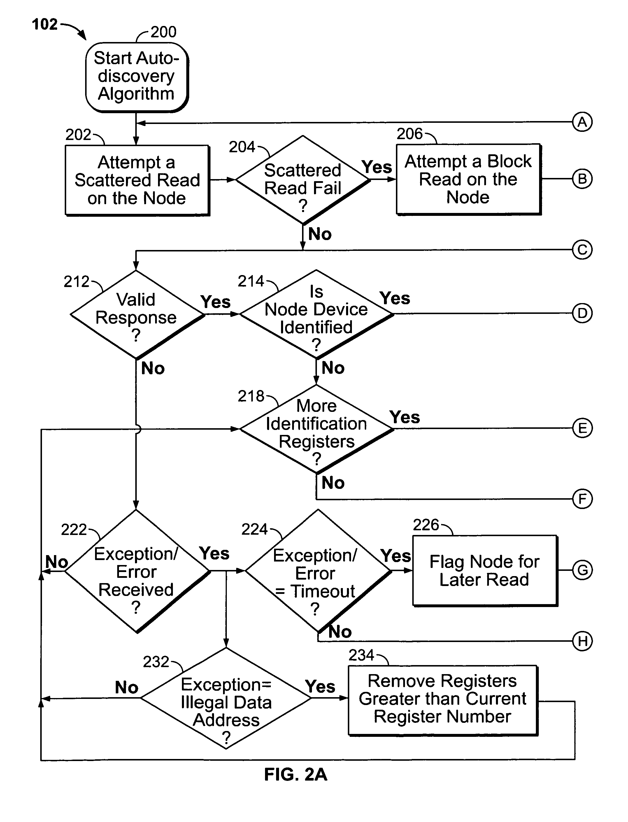
An auto-discovery algorithm attempts a scattered-read of register addresses of a device in a utility monitoring system whose identity is unknown to a computer system. If the scattered read is successful, and data from the device includes a device ID code that is matched against a lookup table of devices. If unsuccessful, the algorithm attempts a block-read, and if unsuccessful, iteratively checks each register against the lookup table to determine whether a match exists until either one is found or the device reports an illegal data address exception, whereupon the algorithm stops attempting to read from subsequent addresses. The algorithm analyzes the response from the communications driver of the computer system to determine whether the response is valid, and if not, what type of exception is reported. If a timeout occurs, the algorithm flags the device for a later retry scan, and moves on to attempt to discover the next device.

Description

FIELD OF THE INVENTION[0001]This invention is directed generally to auto-discovery of devices, and, more particularly, to auto-discovery of utility monitoring devices in a utility monitoring system.BACKGROUND OF THE INVENTION[0002]A utility monitoring system may include utility monitoring devices capable of communicating data to a central computer system that receives the data for storage, analyses or reporting. The central computer system must learn the identity of all of the utility monitoring devices so that it can approve receipt of their monitored data and to know where to go within a known device to find specific data. For example, the A-phase rms voltage may be located in one register in one device and an entirely different register in another device. Knowing the device identity allows the central computer system to also know the device's register layout configuration from a known library of register lists and thereby access the data stored in the device's registers quickly a...

Claims


Application Information

Patent Timeline
Patent Type & Authority Applications(United States)
IPC IPC(8): G06F15/177
CPCG01D4/004Y04S20/322Y02B90/242Y02B90/20Y04S20/30
Inventor MCQUILLAN, JAYMEBICKEL, JON A.
Owner SQUARE D CO
Learn More