Vacuum unit for steam sterilizer

Active Publication Date: 2009-11-26
R V INDS
View PDF4 Cites 7 Cited by
  • Summary
  • Abstract
  • Description
  • Claims
  • Application Information

AI Technical Summary

Benefits of technology

[0014]By incorporation of the above-mentioned features, the vacuum unit in accordance with the invention can achieve a high level of vacuum suitable for operation of a steam sterilizer, rapidly, efficiently, and with a greatly reduced rate of water consumption.

Problems solved by technology

However, the significant water requirements of vacuum equipment associated with steam sterilizers have caused environmental concerns, especially in arid geographic areas.

Method used


Image

  • Vacuum unit for steam sterilizer
  • Vacuum unit for steam sterilizer
  • Vacuum unit for steam sterilizer

Examples


Embodiment Construction

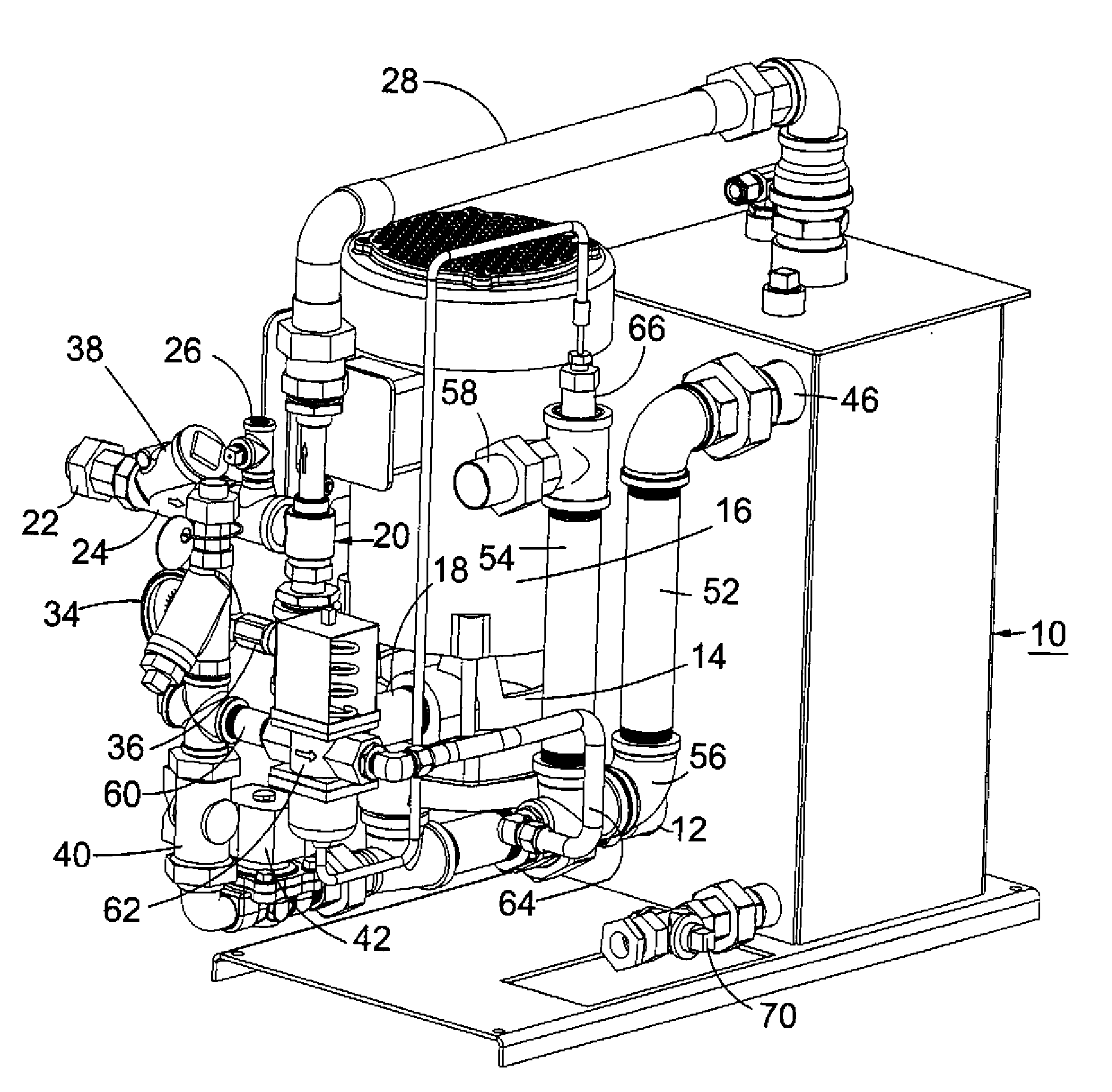
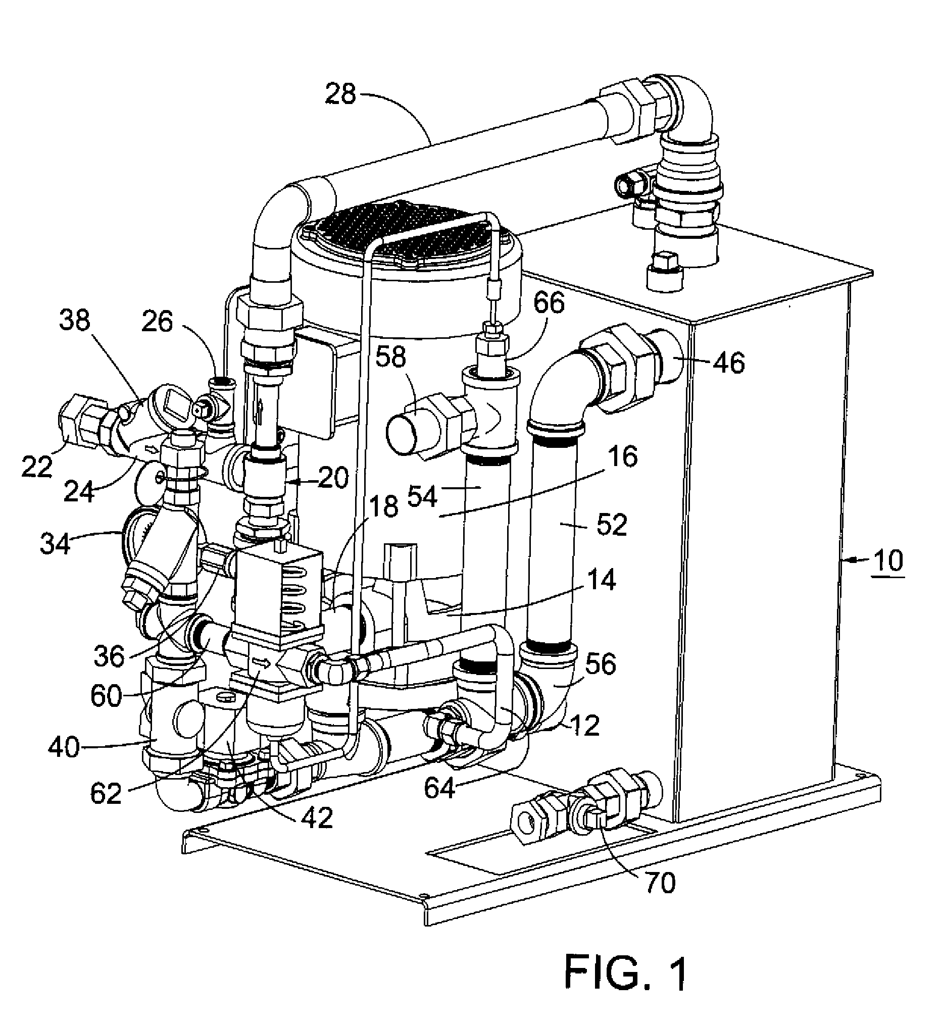
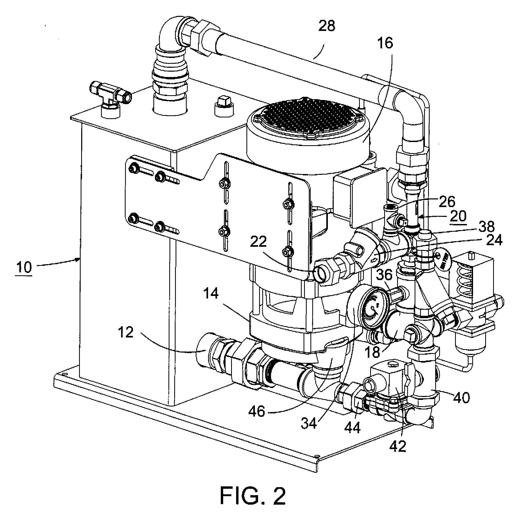
[0020]As shown in FIGS. 1-3, the vacuum unit comprises a tank 10, which serves as a water reservoir. Water is drawn from the tank, through a tank outlet 12, by a pump 14 driven by an electric motor 16. The outlet 18 of the pump leads to an ejector assembly 20, which comprises a restricted passage. The flow of water through the restricted passage produces a pressure drop, drawing a vacuum in pipe 22, which is connectible to the vacuum chamber of a steam sterilizer (not shown). Pipe 22 includes a check valve 24. Another inlet 26 is provided between the check valve and the ejector for drawing a vacuum for opening pressure-operated door seals in the sterilizer.

[0021]Water exiting the ejector is returned to the tank 10 through a pipe 28. Thus, a closed circuit is provided for circulation of water from the tank, through the pump and ejector, and back to the tank.

[0022]Because the ejector draws air, steam and water vapor from the sterilizer, the fluid exiting the ejector will contain air a...


PUM


Abstract

In a vacuum unit for use in drawing a vacuum on a steam sterilizer, a pump circulates water through an ejector and a reservoir. Fresh water is injected at the pump inlet to maintain a low temperature in the ejector so that it can operate efficiently. Excess water is taken from a location adjacent the bottom of the reservoir through an internal dip tube, and passed through a U-shaped conduit that serves as a condensate trap. To maintain the water discharge temperature below a predetermined level, fresh water is injected into the U-shaped conduit through a valve controlled by a temperature sensor downstream from the water injection point.

Description

FIELD OF THE INVENTION[0001]This invention relates to vacuum systems, and particularly to improvements for reducing water consumption in the operation of vacuum systems used to withdraw air and condensate from steam sterilizers.BACKGROUND OF THE INVENTION[0002]Steam sterilizers, also referred to as “autoclaves,” are widely used in a variety of applications for eliminating contaminating microorganisms from articles such as surgical instruments and other hospital equipment, laboratory equipment, and pharmaceutical and medical products.[0003]In the operation of a steam sterilizer, after charging the sterilizer chamber with articles to be sterilized, air is drawn out of the chamber by applying a vacuum. Drawing of the vacuum is discontinued, and steam is then injected into the chamber. After the articles in the chamber have been exposed to steam for a sufficient time, drawing the vacuum can be resumed to remove steam, water vapor and condensate. In some cases, the cycle consisting of dr...

Claims


Application Information

Patent Timeline
IPC IPC(8): A61L2/00F17D1/00F04F3/00A61L2/26
CPCA61L2/07A61L2/26A61L2202/24A61L2202/21A61L2202/122Y10T137/85954Y10T137/86083
Inventor BRUGNOLI, ADAM L.BROWNLOW, III, KENNETH G.DEMARRA, PHILLIP B.BECKER, TODD A.GONZALEZ, DANIELDILLOW, ANDREW J.CINQUEGRANA, ALAN C.
Owner R V INDS
Why Eureka
Try Eureka