
Method and apparatus for high pressure radial pulsed jetting of lateral passages from vertical to horizontal wellbores

a technology of lateral passages and pulses, which is applied in the direction of drilling machines and methods, fluid removal, and wellbore/well accessories, etc., can solve the problems of inability to vertically drill wells, undesirable or practical, and steel tool positioning and operation strings are typically incapable of being used in deviated sections of wellbores, so as to facilitate the application of radial jetting

Active Publication Date: 2009-11-26
SCHLUMBERGER TECH CORP
View PDF20 Cites 40 Cited by
  • Summary
  • Abstract
  • Description
  • Claims
  • Application Information

AI Technical Summary

Benefits of technology

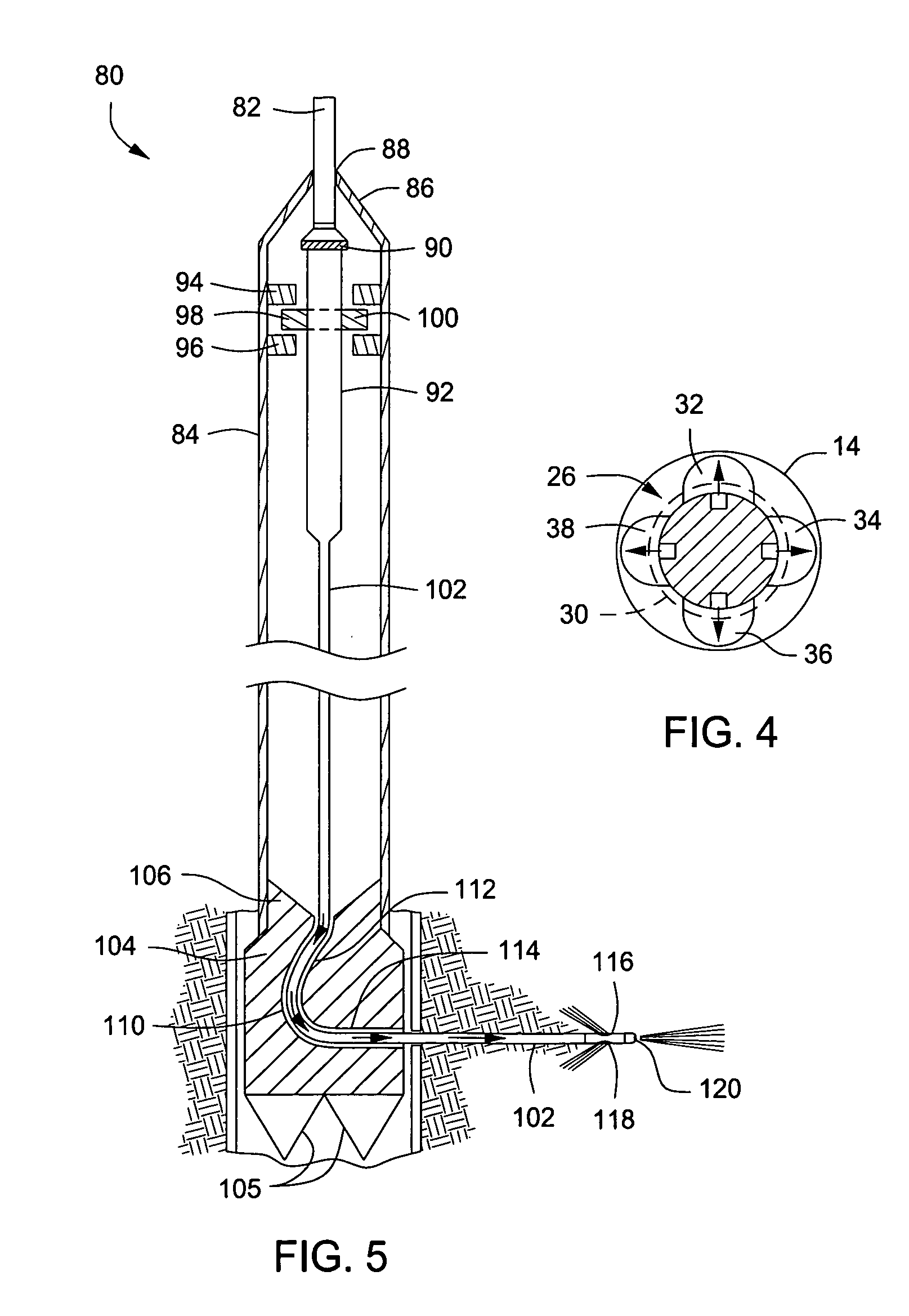
The present invention provides a novel method and apparatus for applying radial jetting in deeper and highly deviated wells for subsurface formation of lateral passages. The invention allows for the use of a conveyed radial hydraulic fluid jetting system that can be easily oriented and positioned within a wellbore, and can be used with different types of wellbore casing. The system includes a cutting mechanism and a jetting mechanism that can be independently run into a wellbore and used sequentially for casing cutting and passage formation. The invention also allows for the installation of multiple lateral passages from a single wellbore casing, and the use of a seating mechanism to facilitate the orientation and positioning of the system. The invention provides a more efficient and effective method for applying radial jetting in wellbore construction.

Problems solved by technology

In many cases however, it is not possible, desirable or practical to drill wells vertically, so the wells or sections of the wellbores are drilled so as to be inclined or deviated from the vertical.
Steel tool positioning and operation strings are typically incapable of use in deviated sections of wellbores since they will not readily follow the contour of inclined wellbore sections.
This is disadvantageous because of the excessive wear and high maintenance that occurs as very high jetting fluid medium pressures that are required to develop the necessary fluid pressure for jet blasting of lateral passages.
This passage jetting process is typically rather slow, due to the steady fluid pressure that is employed.
However, it is detrimental to the jet blasting equipment, including coiled tubing or jointed tubing to develop high pressure pulsing pressure at the surface to yield the desired high pressure pulsing at the lateral passage depth of a wellbore.
The use of abrasives in jet blasting fluid is especially detrimental to the service life of surface based pumping equipment.
While such mechanical drilling systems can and have been employed, equipment and processes for drilling multiple lateral passages into a surrounding formation, without retrieving the drilling apparatus from the wellbore between each passage drilling operation, have not been used to date.
Such operations are quite slow and expensive in comparison with apparatus and methods for jet blasting lateral passages.
A problem with existing lateral passage forming products and techniques is that they have limited repeatability due to the uncertainty of actual penetration in more dense and compressive rock components.
High pressure jet drills are unpredictable in their actual performance of jetting in the downhole environment due to the formation compressive factors that typically exist.
Another problem with existing lateral passage forming products and techniques is that they require multiple trips into a well to jet form a plurality of lateral passages into the formation, and for rotational orientation of a passage jetting mechanism within a wellbore so that the resulting lateral passages are oriented along predetermined azimuths.
A significant problem with existing lateral passage forming systems and techniques is that the use of abrasive materials in the passage jetting fluid is typically very damaging to the surface fluid pumping equipment and adversely affects the porosity and permeability of the producing formations and thus is detrimental to the productivity potential of the well.
The use of basic fluids for lateral passage jetting activity can be very detrimental to the producing formation.

Method used


Image

  • Method and apparatus for high pressure radial pulsed jetting of lateral passages from vertical to horizontal wellbores
  • Method and apparatus for high pressure radial pulsed jetting of lateral passages from vertical to horizontal wellbores
  • Method and apparatus for high pressure radial pulsed jetting of lateral passages from vertical to horizontal wellbores

Examples


Embodiment Construction

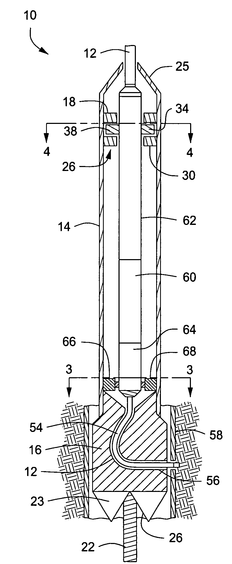
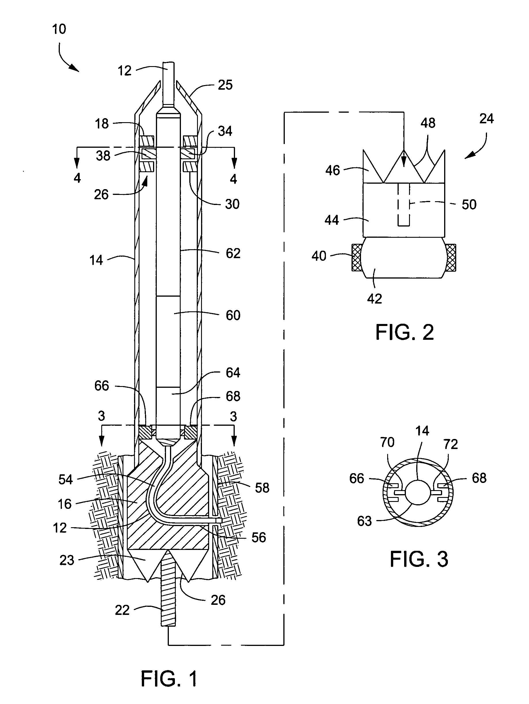
[0044]Referring now to the drawings and first to FIGS. 1 and 2, a casing cutting component of the present invention is shown generally at 10 and is conveyed into and from a wellbore by means of coiled tubing 12 that is controlled by coiled tubing handling equipment located at the surface. Alternatively, a tool conveyance string may be defined by multiple interconnected lengths of straight tubing without departing from the spirit and scope of the present invention. The casing cutting component or mechanism 10 has an outer tubular conveyance body 14, with a deflector or deflector shoe member 16 provided at its lower end. The outer tubular conveyance section can be constructed in several ways. It can be formed of commercially available production tubing and can have a size greater than the size of conventional coiled tubing or may be provided in the form of manufactured sections of tubes that are assembled to form a desired tubing string length. Internal components are preferably mille...


PUM


Abstract

An apparatus and system that permits radial passages and lateral passages to be jetted into surrounding subsurface formation from existing or new wells. The system employs a casing cutting component that positionable by an anchored indexing device downhole to permit the formation of accurately positioned openings in the well casing. The system employs a passage jetting component employing extreme high jet fluid pressures and a method that allows for the downhole manipulation of the components so that the radial and lateral passages are achieved by minimum pulling work on casing, tubing or other components. The system is fully controllable and reduces dramatically the margins of error and failure that are inherent of the present day systems used for radial drilling.

Description

[0001]Applicant hereby claims the benefit of U.S. Provisional Application Ser. No. 61 / 128,254 filed on May 20, 2008 by Henk H. Jelsma and entitled “Device to Allow High Pressure Radial Pulsed Jetting in Vertical to Horizontal Wells”, which Provisional Application is incorporated herein by reference for all purposes.BACKGROUND OF THE INVENTION[0002]1. Field of the Invention[0003]The present invention relates generally to drilling activities for petroleum production wells and to renovation activities for existing wells to enhance the production capability thereof. More specifically, the present invention concerns a method and apparatus for conveyed high pressure hydraulic radial pulsed jetting in vertical to horizontal boreholes for jet formation of specifically oriented lateral passages in a subsurface formation surrounding a wellbore.[0004]2. Description of the Prior Art[0005]Of particular interest to the present invention is the subject matter of U.S. Pat. No. 7,422,059, issued to ...

Claims


Application Information

Patent Timeline
Patent Type & Authority Applications(United States)
IPC IPC(8): E21B7/18E21B43/11E21B29/00E21B43/119
CPCE21B43/114E21B7/046
Inventor JELSMA, HENK H.
Owner SCHLUMBERGER TECH CORP
Learn More