Electric Motor and Method for Manufacturing an Electric Motor for a Motor Vehicle Actuator Drive

a technology for actuator drives and electric motors, which is applied in the manufacture of stator/rotor bodies, magnetic circuit rotating parts, and shape/form/construction of magnetic circuits, etc. it can solve the problems of affecting the operation of the respective motor, so as to achieve the effect of reducing the risk of a gap forming between the housing wall and the stator, and reducing the risk of a gap

Inactive Publication Date: 2009-11-26
BROSE FAHRZEUGTEILE GMBH & CO KG HALLSTADT (DE)
View PDF12 Cites 38 Cited by
  • Summary
  • Abstract
  • Description
  • Claims
  • Application Information

AI Technical Summary

Benefits of technology

[0006]The object of the invention is accordingly to specify an electric motor and a method for manufacturing an electric motor for a motor vehicle actuator drive which ensure that the stator assembly is reliably secured in the motor housing, and which also permit dismounting of the motor without damage to the individual assemblies, but at the same time gaps are to be reliably prevented from forming between the stator assembly and the housing wall.

Problems solved by technology

A disadvantage of attachment of the stator assembly in the motor housing by bonding or by using a sealing compound is that disassembly of the respective motor, for example for repair purposes, is not possible without damaging it.
As a result, there is the risk of the housing wall and surface of the stator being pressed apart from one another and of a gap forming between them.
In this case, air gaps which are produced between the housing wall and the stator are very disruptive.
The transfer of heat from the stator to the housing and from there to the outside is also impeded by air gaps between the stator and the housing, and this in turn has an adverse effect on the power of the electric motor.

Method used


Image

  • Electric Motor and Method for Manufacturing an Electric Motor for a Motor Vehicle Actuator Drive
  • Electric Motor and Method for Manufacturing an Electric Motor for a Motor Vehicle Actuator Drive
  • Electric Motor and Method for Manufacturing an Electric Motor for a Motor Vehicle Actuator Drive

Examples


first embodiment

[0037]According to this first embodiment, described above in conjunction with FIGS. 1 and 3, the stator assembly is built up with a large number of individual tooth segments.

[0038]FIG. 4 shows two individual tooth segments such as are provided in the first embodiment, in a perspective illustration, individually and unwrapped. The individual tooth segment which is illustrated on the left-hand side of FIG. 4 is a segment which has, in the region of its tooth back, a notch 4d which is not provided to hold a securing pin. The individual tooth segment illustrated on the right-hand side in FIG. 4 is a segment which is equipped in the region of its tooth back with a relatively wide notch 4c, for the purpose of holding a securing pin. The bulges and recesses 4e / 4f can also be clearly seen on the side faces of the tooth backs, and they engage one in the other when the individual tooth segments are joined.

[0039]In a subsequent step, such as is illustrated in FIG. 5, these individual teeth are...

second embodiment

[0042]After this, in a second step S2, a stator assembly 4 is inserted into the motor housing 2 in the axial direction in accordance with the first or second embodiment described above.

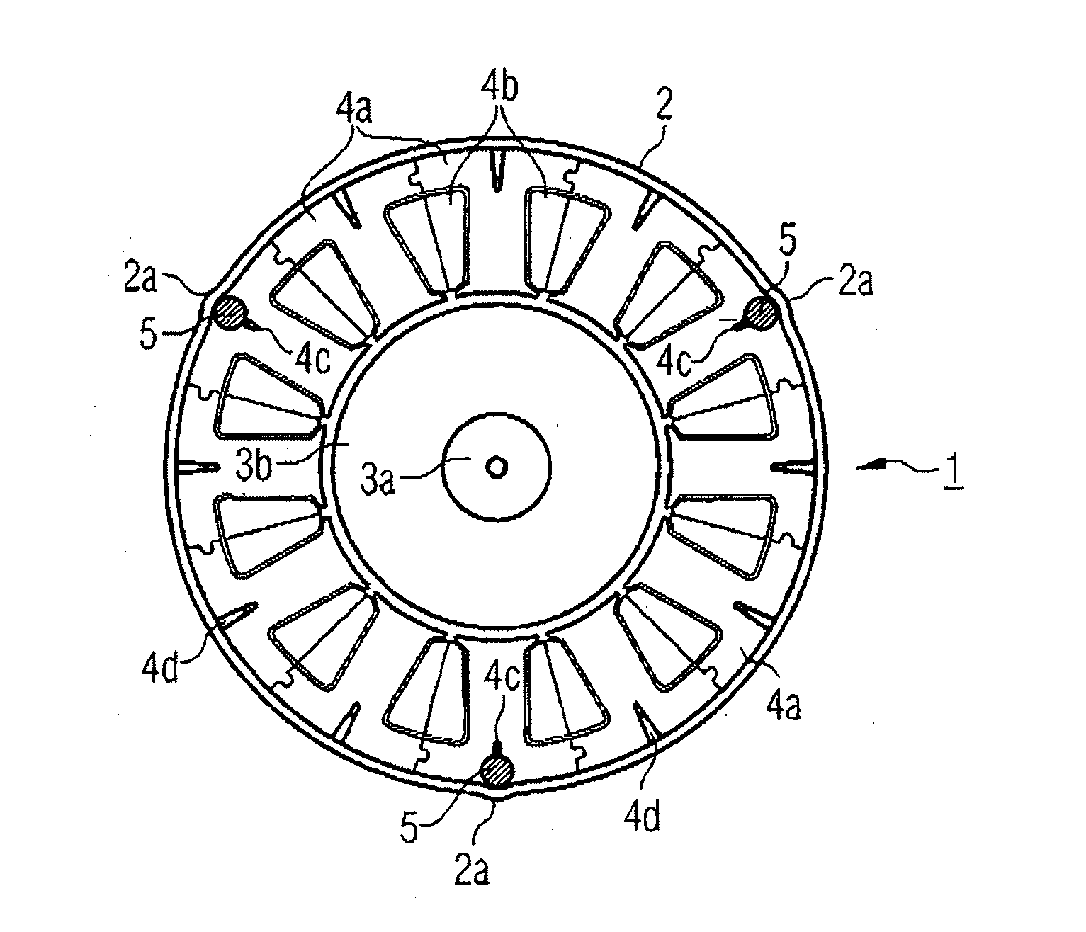
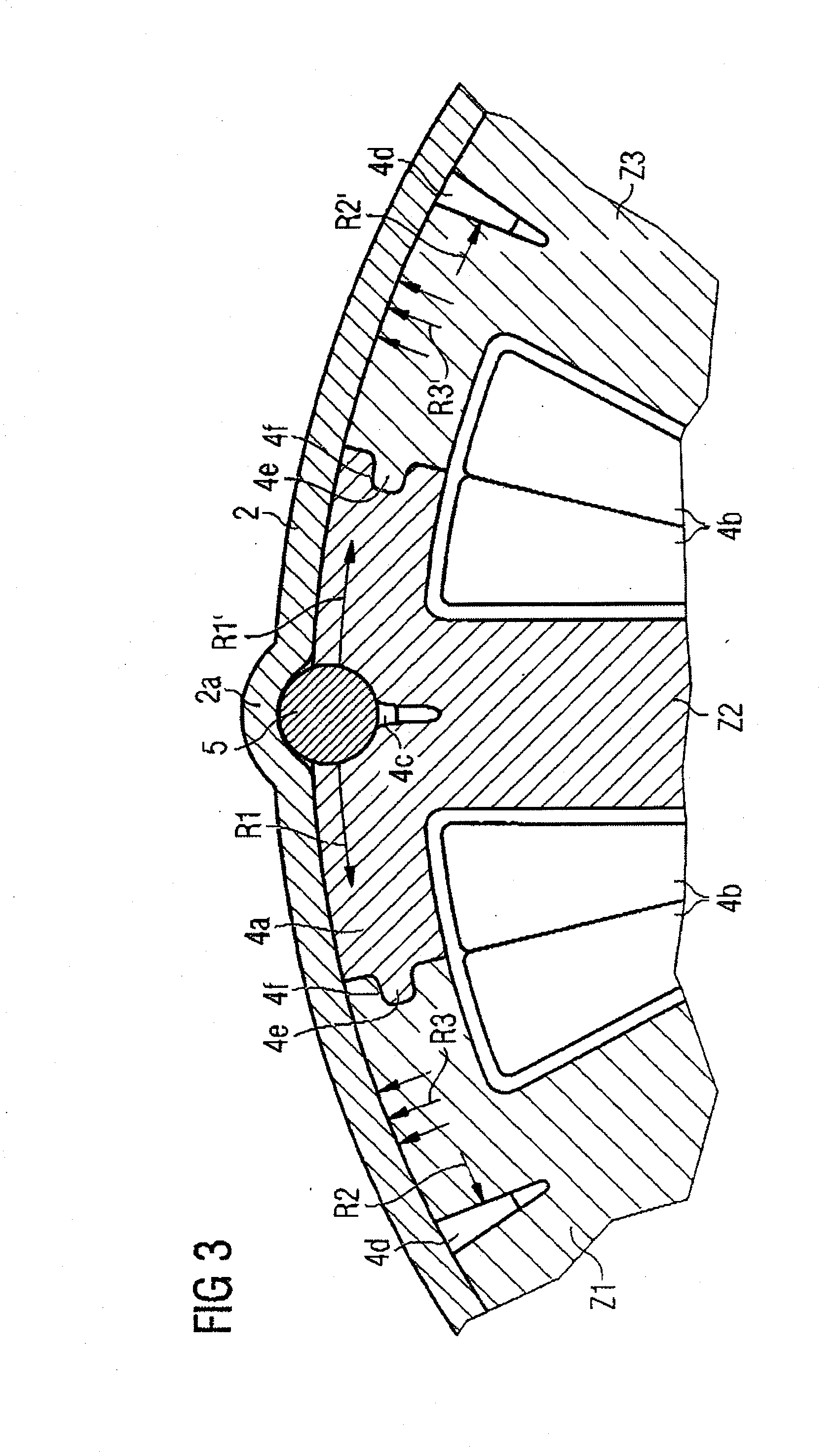
[0043]If the stator assembly 4 is inserted into the motor housing 2, its attachment in the motor housing 2 is carried out in such a way that in a third step S3 a number of securing pins 5 are introduced in the axial direction into notches 4c which are provided in the region of the tooth back of individual stator teeth 4a. In this context, a total of three securing pins, which are each spaced apart from one another by 120° in the circumferential direction of the stator assembly 4, are preferably inserted.

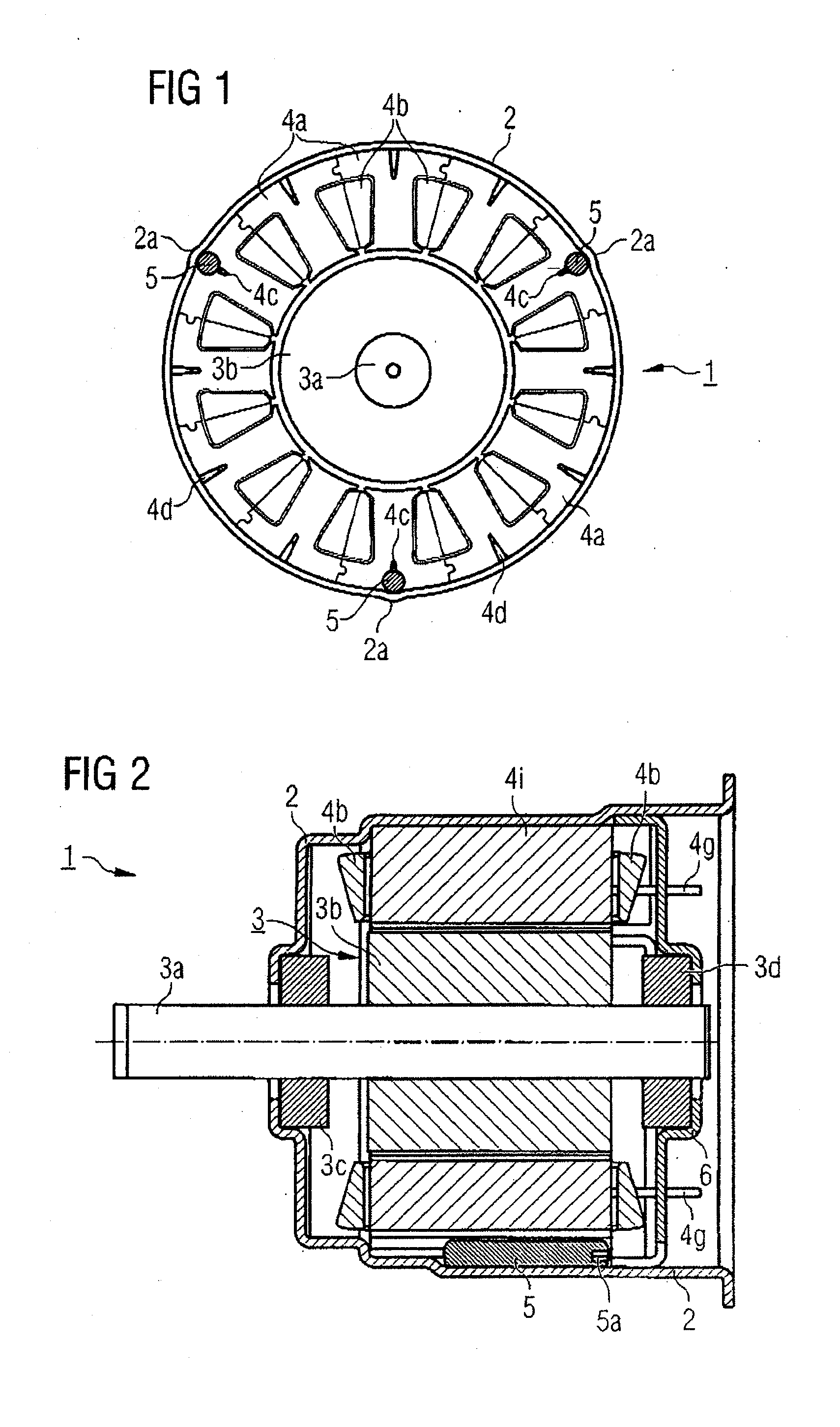
[0044]Depending on the embodiment of the motor housing 2, it may be necessary firstly to mount an end plate with a bearing 3c for the rotor shaft 3a on an end side of the motor housing 2 in a further mounting step S3′, illustrated by dashed lines in FIG. 8.

[0045]In the next mounting step S4, a rotor as...


PUM

PropertyMeasurementUnit
forcesaaaaaaaaaa
circumferenceaaaaaaaaaa
forceaaaaaaaaaa

Abstract

The invention relates to an electric motor and a method for manufacturing an electric motor for a motor vehicle actuator drive. The electric motor has a motor housing, a rotor assembly and a stator assembly. The stator assembly has stator teeth which are each provided with a notch in the region of their tooth back. A securing pin, which secures the stator assembly in the motor housing, is inserted into each of these notches.

Description

FIELD OF THE INVENTION[0001]The invention relates to an electric motor and to a method for manufacturing an electric motor for a motor vehicle actuator drive.BACKGROUND OF THE INVENTION[0002]Electric motors for motor vehicle actuator drives are already known. They are used, for example, as window lifter motors, as a drive motor for adjusting the push and tilt sunroof or for assisting the steering process of a motor vehicle. A specific design of such a motor is, for example, a brushless commutated motor with an internal rotor and an electrically excited stator. Such a motor generally has a motor housing, a stator assembly which is inserted into the motor housing and has wound stator teeth, and a rotor assembly which is inserted concentrically into the motor housing, within the stator assembly. The rotor assembly includes a rotor shaft and a rotor packet which is attached to the rotor shaft. Depending on the design, the rotor assembly can also be excited electrically with windings or ...

Claims


Application Information

Patent Timeline
Patent Type & Authority Applications(United States)
IPC IPC(8): H02K1/18H02K15/02
CPCH02K1/148Y10T29/49009H02K1/185
Inventor BUBAN, TOBIAS
Owner BROSE FAHRZEUGTEILE GMBH & CO KG HALLSTADT (DE)
Why Eureka
Try Eureka