Method and Apparatus for Implementing EIT Magnetometry

a magnetometry and apparatus technology, applied in the field of magnetometry, can solve the problems of requiring a costly apparatus, large and difficult to move, and requiring superconducting electromagnets, etc., and achieves the effects of reducing the number of johnson noise, and reducing the noise of johnson nois

Active Publication Date: 2009-11-26
ENTANGLEMENT TECH
View PDF2 Cites 40 Cited by
  • Summary
  • Abstract
  • Description
  • Claims
  • Application Information

AI Technical Summary

Benefits of technology

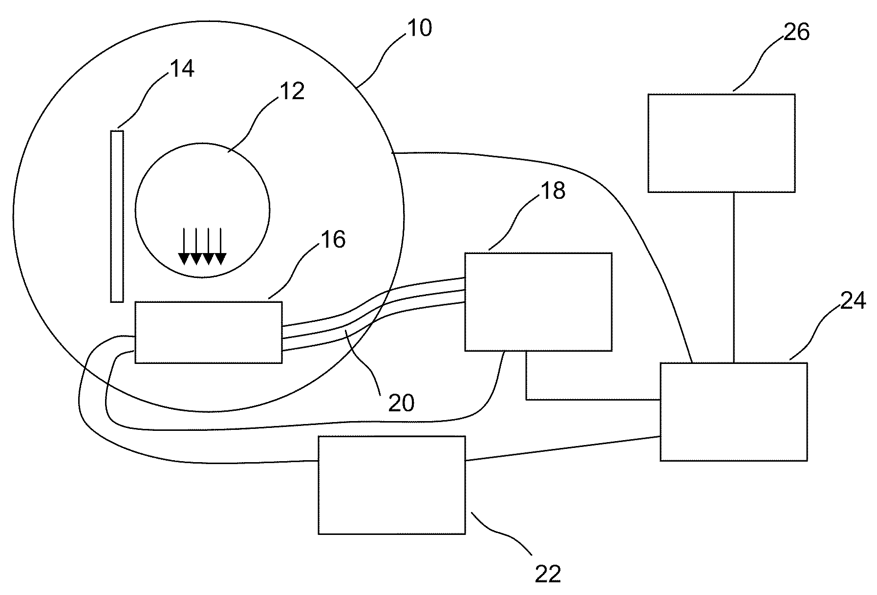
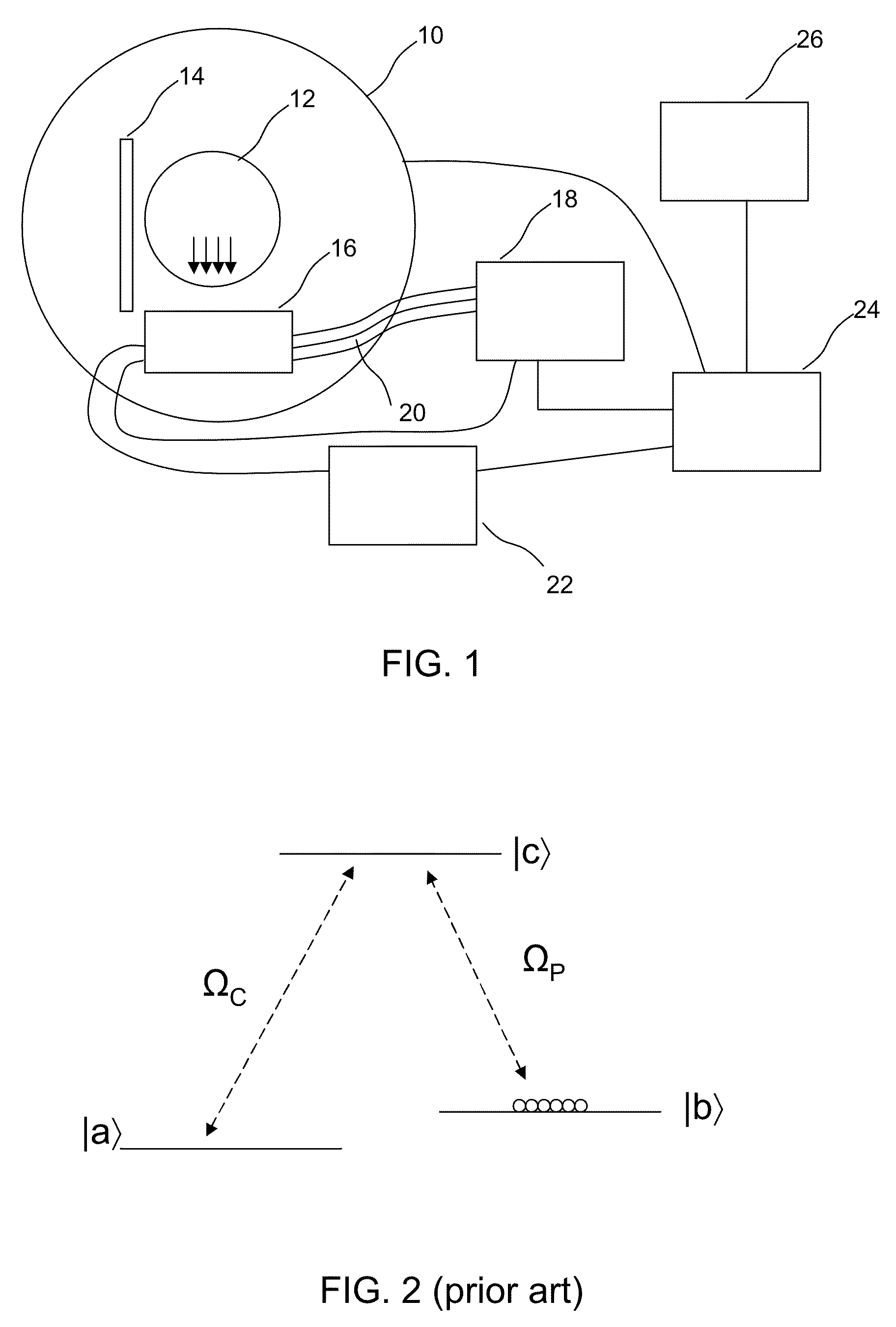
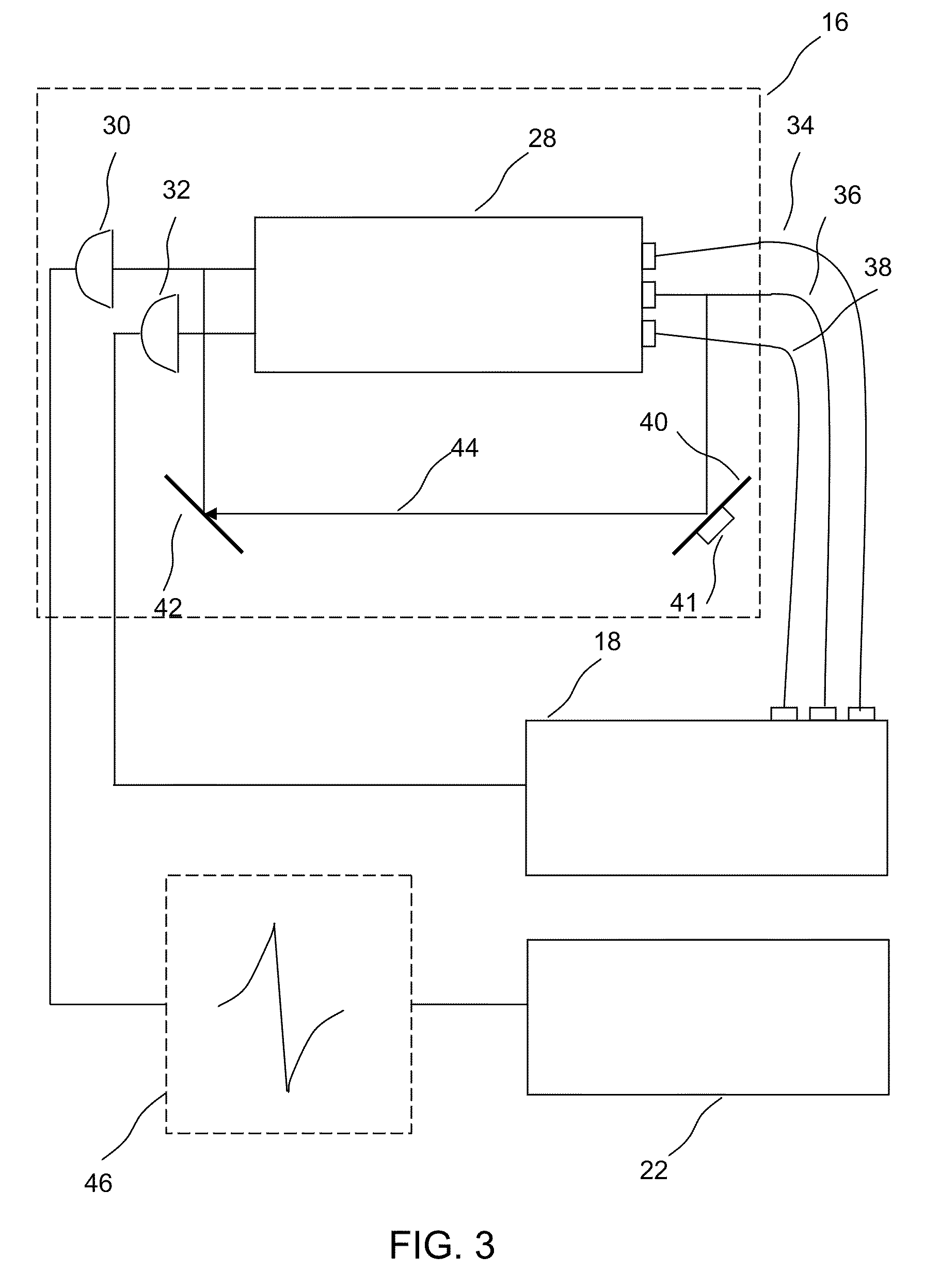
[0017]A magnetometer is provided comprising an atomic vapor in an enclosure, a source of light for preparing the vapor into a state exhibiting electromagnetically induced transparency, a first laser beam passing through the atomic vapor, a phase detector for detecting changes in phase of the first laser beam, and a controller which controls the light source and laser beam and receives the information detected by the phase detector in order to compute from those changes in phase a magnetic field strength. The source of light is capable of producing light which places the vapor in a state exhibiting electromagnetically induced transparency in the presence of a selected background magnetic field. The phase detector is capable of extracting information from which magnetic field strength can be determined in the presence of a background field greater than about 0.001 T. Operation in the presence of a background field helps make this magnetometer suitable for diagnostic imaging applications.

Problems solved by technology

Superconducting electromagnets thus require a costly apparatus and are large and difficult to move.
For large fields with inductive coil detection, noise is limited by body Johnson noise.
For small fields coil Johnson noise becomes significant.
However, SQUID-based magnetometers require very low temperatures and associated cooling equipment.
Cryogenic equipment, in addition to the problems of cost, may have filling factor problems; thermal isolation requirements of sample from detector are a potential concern for signal.
There are a number of difficulties with conventional atomic gas magnetometers in the MRI application.
One difficulty is that some atomic gas magnetometers require an extremely low background field, whereas conventional MRI detects a small time-varying magnetic field in the presence of a large DC background magnetic field.

Method used


Image

  • Method and Apparatus for Implementing EIT Magnetometry
  • Method and Apparatus for Implementing EIT Magnetometry
  • Method and Apparatus for Implementing EIT Magnetometry

Examples


Embodiment Construction

[0026]Definitions and Overview

[0027]It is to be understood that, unless otherwise indicated, this invention is not limited to specific arrangements of optical or electronic equipment or specific working materials. It is also to be understood that the terminology used herein is for the purpose of describing particular embodiments only, and is not intended to be limiting.

[0028]In describing and claiming the present invention, the following terminology will be used in accordance with the definitions set out below.

[0029]The singular forms “a,”“an,” and “the” include plural referents unless the context clearly dictates otherwise. Thus, for example, reference to “a laser beam” includes not only a single laser beam but also two or more laser beams that may or may not be combined in a single composition, reference to“a polarizing filter” includes a single polarizing filter as well as two or more polarizing filters that may or may not be combined, and the like.

[0030]Introductory Information ...


PUM


Abstract

A magnetometer is provided comprising an atomic vapor in an enclosure, a source of light for preparing the vapor into a state exhibiting electromagnetically induced transparency, a first laser beam passing through the atomic vapor, a phase detector for detecting changes in phase of the first laser beam, and a controller which controls the light source and laser beam and receives the information detected by the phase detector in order to compute from those changes in phase a magnetic field strength in the presence of a selected background magnetic field of at least 0.001 T. Operation in the presence of a background field helps make this magnetometer suitable for diagnostic imaging applications.

Description

CROSS-REFERENCE TO RELATED APPLICATIONS[0001]This application claims priority to U.S. Provisional Application Ser. No. 61 / 055,010, filed May 21, 2008, which is incorporated by reference in its entirety.TECHNICAL FIELD[0002]This invention relates generally to magnetometry and also to the diagnostic imaging of the human body.BACKGROUND[0003]Magnetic resonance imaging (MRI) has come into very wide use for the imaging of the human body, for example, for the diagnosis of soft tissue abnormalities. MRI as currently practiced requires a large magnet capable of producing spatially uniform fields in excess of 1 Tesla, commonly fields of 1.5 Tesla and up to at least 3 Tesla. To generate such large uniform fields, superconducting electromagnets are normally employed. Commercially viable superconducting electromagnets are only superconducting at temperatures near 4 Kelvin and below. Superconducting electromagnets thus require a costly apparatus and are large and difficult to move.[0004]MRI was ...

Claims


Application Information

Patent Timeline
Patent Type & Authority Applications(United States)
IPC IPC(8): G01R33/24G01R33/02G01R33/44G01R33/28
CPCG01R33/032G01R33/32G01R33/24G01R33/26
Inventor TUCHMAN, ARI K.
Owner ENTANGLEMENT TECH
Why Eureka
Try Eureka