Transparent see-through display device

a display device and transparent technology, applied in the field of transparent see-through display devices, can solve the problems of difficult to implement transparent displays using current display technologies, surface light emitting sources are a problem, and achieve the effect of minimizing beam refraction

Inactive Publication Date: 2009-11-26
KOREA ADVANCED INST OF SCI & TECH
View PDF7 Cites 26 Cited by
  • Summary
  • Abstract
  • Description
  • Claims
  • Application Information

AI Technical Summary

Benefits of technology

[0031]The plurality of patterns may be sparsely spaced apart from one another to minimize refraction of beams which are incident to the upp

Problems solved by technology

However, it is difficult to implement the transparent displays using current display technologies.
However, it is difficult to implement transparent displays because of main components such as a back light apparatus and a color filter.
However, the surface light emitting source is a problem in implementing a transparent display.
However, when a diffusion sheet is formed on the light guide plite, the optical patterns cause distortion of transmitted beams, and therefore, it is difficult to implement a transparent display.
Therefore, the diffusion sheet is a primary factor in blocking implementation of a transparent display.
Further, a color filter of the LCD has a transmittance of 25% or less, and its efficiency is low.
For this reason, it is difficult to ensure transparency.
However, the electrodeposition has a critical problem in uniformly arranging pixels and manufacturing large-sized

Method used


Image

  • Transparent see-through display device
  • Transparent see-through display device
  • Transparent see-through display device

Examples


first embodiment

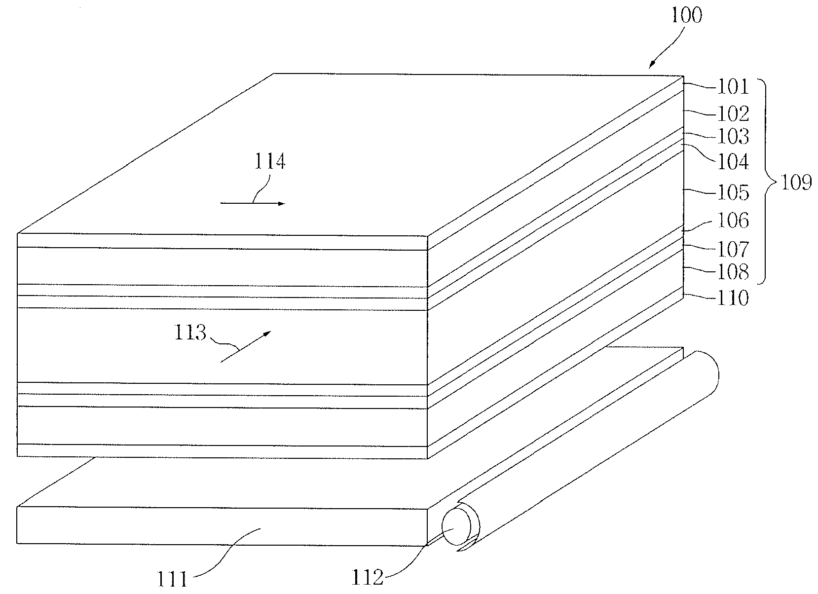
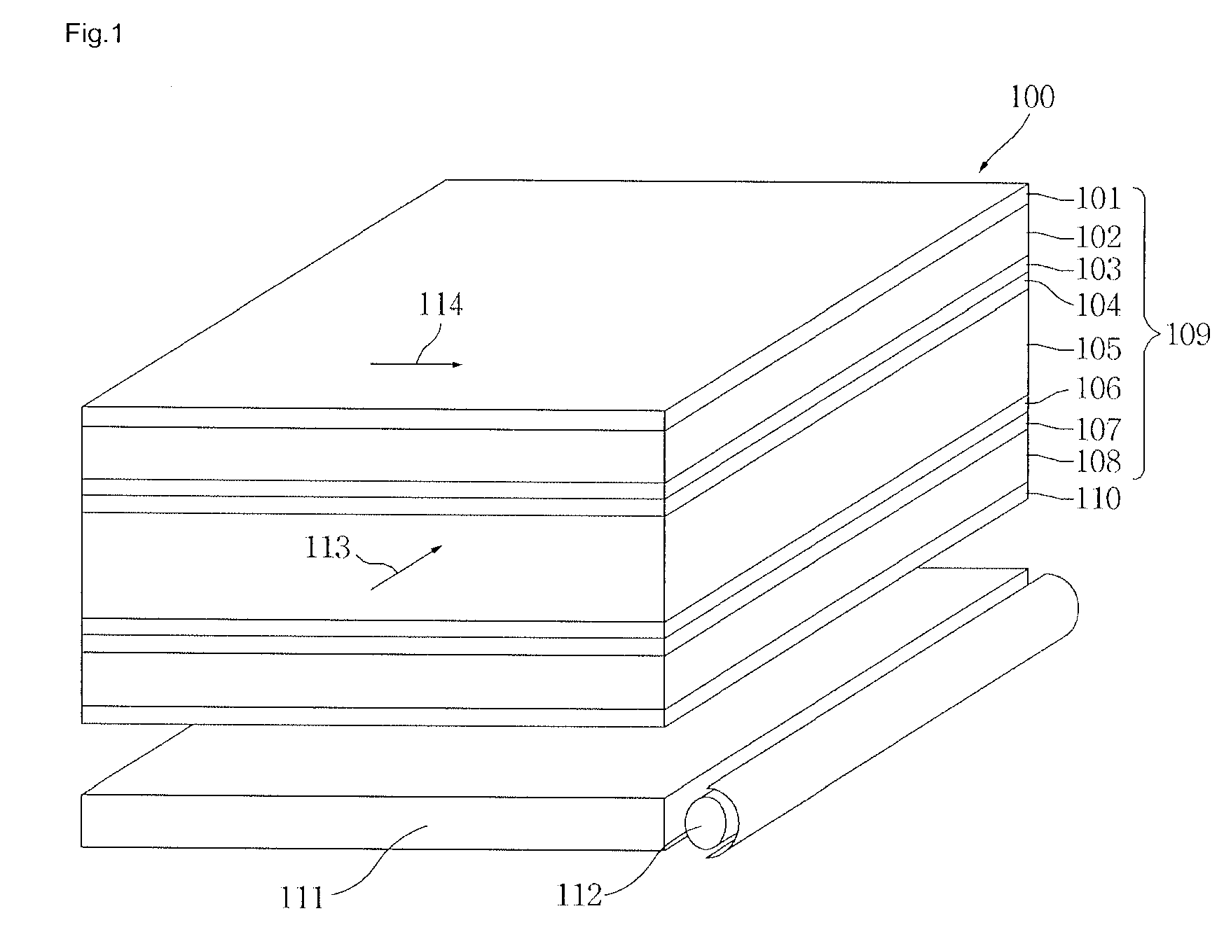
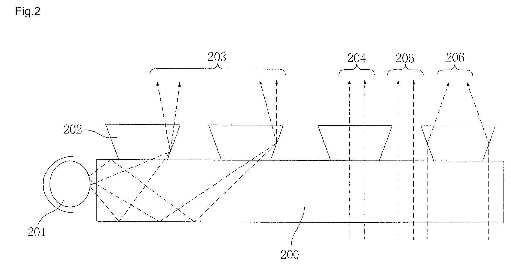
[0044]Hereinafter, a transmissive see-through display device will be described with reference to the accompanying drawings.

[0045]FIG. 1 is a cross-sectional perspective view illustrating the structure of a transmissive see-through display device according to a first embodiment. FIG. 2 is a view illustrating an embodiment of the structure of a transparent light guide plate in the see-through display device. FIG. 3 is a view illustrating another embodiment of the structure of a transparent light guide plate in the see-through display device. FIG. 4 is a view illustrating still another embodiment of the structure of a transparent light guide plate in the see-through display device. FIG. 5 is a view illustrating an embodiment of the operation when a see-througll display device is in a transmitting state. FIG. 6 is a view illustrating an embodiment of the operation when a see-through display device is in a blocking state. FIG. 7 is a view illustrating an embodiment of the display state ...

second embodiment

[0073]Hereinafter, a transmissive see-through display device will be described with reference to the accompanying drawings.

[0074]FIG. 9 is a cross-sectional perspective view illustrating the structure of a transmissive see-through display device according to a second embodiment. FIG. 10 is a view illustrating an embodiment of the operation when a see-through display device is in a transmitting state. FIG. 11 is a view illustrating an embodiment of the operation when a see-through display device is in a blocking state.

[0075]FIG. 9 is a cross-sectional perspective view illustrating the structure of a transmissive see-through display device according to a second embodiment.

[0076]As illustrated in FIG. 9, the transmissive see-through display device 900 comprises a transparent optical display device 911.

[0077]The transparent optical display device 911 comprises a pair of first and second transparent plates 904 and 910, which are disposed while being spaced apart from each other at a pre...


PUM


Abstract

There is provided a see-through display device. A see-through display device comprises a liquid crystal plate filled with liquid crystals; first and second orientation plates respectively positioned on upper and lower surfaces of the liquid crystal plate, and controlling an initial alignment state of the liquid crystals; first and second conductive plates respectively positioned on an upper surface of the first orientation plate and a lower surface of the second orientation plate, and being filled with a conductive material; first and second transparent plates respectively positioned on an upper surface of the first conductive plate and a lower surface of the second conductive plate; first and second polarizing plates respectively positioned on an upper surface of the first transparent plate and a lower surface of the second transparent plate; and a transparent light guide plate spaced apart from a lower surface of the second polarizing plate, and allowing beams incident from a light source positioned at one side thereof to be totally reflected and emitted upward. Accordingly, a see-through display device comprises a transparent optical display device and a transparent light guide plate having a light source disposed at one side thereof, so that the display device can be optically transparent even when it is not operated.

Description

CROSS-REFERENCE TO RELATED APPLICATION[0001]This application claims priority to Korean Patent Application No. 10-2008-0046438, filed on May 20, 2008, and all the benefits accruing therefrom under 35 U.S.C. §119, the contents of which in its entirety are herein incorporated by reference.BACKGROUND OF THE INVENTION[0002]1. Field of the Invention[0003]This disclosure relates to a transparent see-through display device, and more particularly, to a device capable of displaying images by allowing background radiation and beams incident to the display device to be exclusively or simultaneously transmitted or blocked.[0004]2. Description of the Related Art[0005]Display devices through which various types of information such as images and characters are visually displayed to human beings have come into the highlight as a core sector in information and communication industries.[0006]In the future, it is expected that displays will require not only conventional ultra-thin, high-resolution and ...

Claims


Application Information

Patent Timeline
IPC IPC(8): G02F1/13357
CPCG02B6/0036G02F2001/133616G02F1/133615G02F1/133616G02F1/1335G02F1/13363
Inventor YOON, JUN-BOCHOI, WON-SEOKLEE, JOO-HYUNG
Owner KOREA ADVANCED INST OF SCI & TECH
Why Eureka
Try Eureka