
Switching power supply with increased efficiency at light load

a technology of switching power supply and light load, which is applied in the direction of electric variable regulation, process and machine control, instruments, etc., can solve the problems of reducing the overall operating efficiency of the power supply, the proportion of switching loss and other consumption for maintaining basic circuit operations is obviously higher, and the loss of switching power supply to the output power is obviously higher. , to achieve the effect of increasing the operating efficiency of the switching power supply

Inactive Publication Date: 2009-11-26
ACBEL POLYTECH INC
View PDF4 Cites 23 Cited by
  • Summary
  • Abstract
  • Description
  • Claims
  • Application Information

AI Technical Summary

Benefits of technology

[0010]To increase the overall operating efficiency of the power supply, an objective of the invention is to provide a switching power supply that can enhance power conversion efficiency at light load by providing a light load power supplying circuit for the light load.
[0015]According to the above-mentioned technique, the voltage of the battery of the light load power supplying circuit is smaller. Therefore, when the load is in a light state, the switching loss of the second DC to DC converter of the light load power supplying circuit is relatively lower than the power output to the load. This thus increases the operating efficiency of the switching power supply at light load.

Problems solved by technology

Since the voltage imposed on the source and drain of the power transistor is equal to the DC power voltage output from the AC to DC converting unit 81, the imposed voltage on and the current flowing through the source and drain result in switching loss when the power transistor is switched on and off.
However, if the load 90 is a light load, the proportion of the switching loss and other consumption for maintaining basic circuit operations to the output power is obviously higher because the output power is small.
As a result, the overall operating efficiency of the power supply drops down.

Method used


Image

  • Switching power supply with increased efficiency at light load
  • Switching power supply with increased efficiency at light load
  • Switching power supply with increased efficiency at light load

Examples


Embodiment Construction

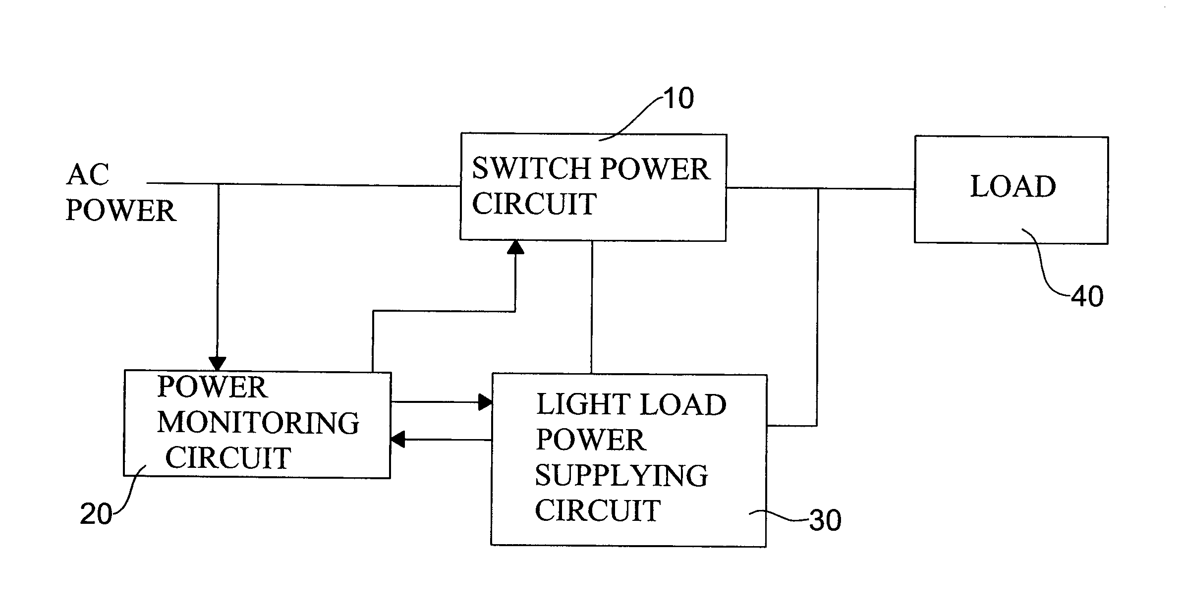
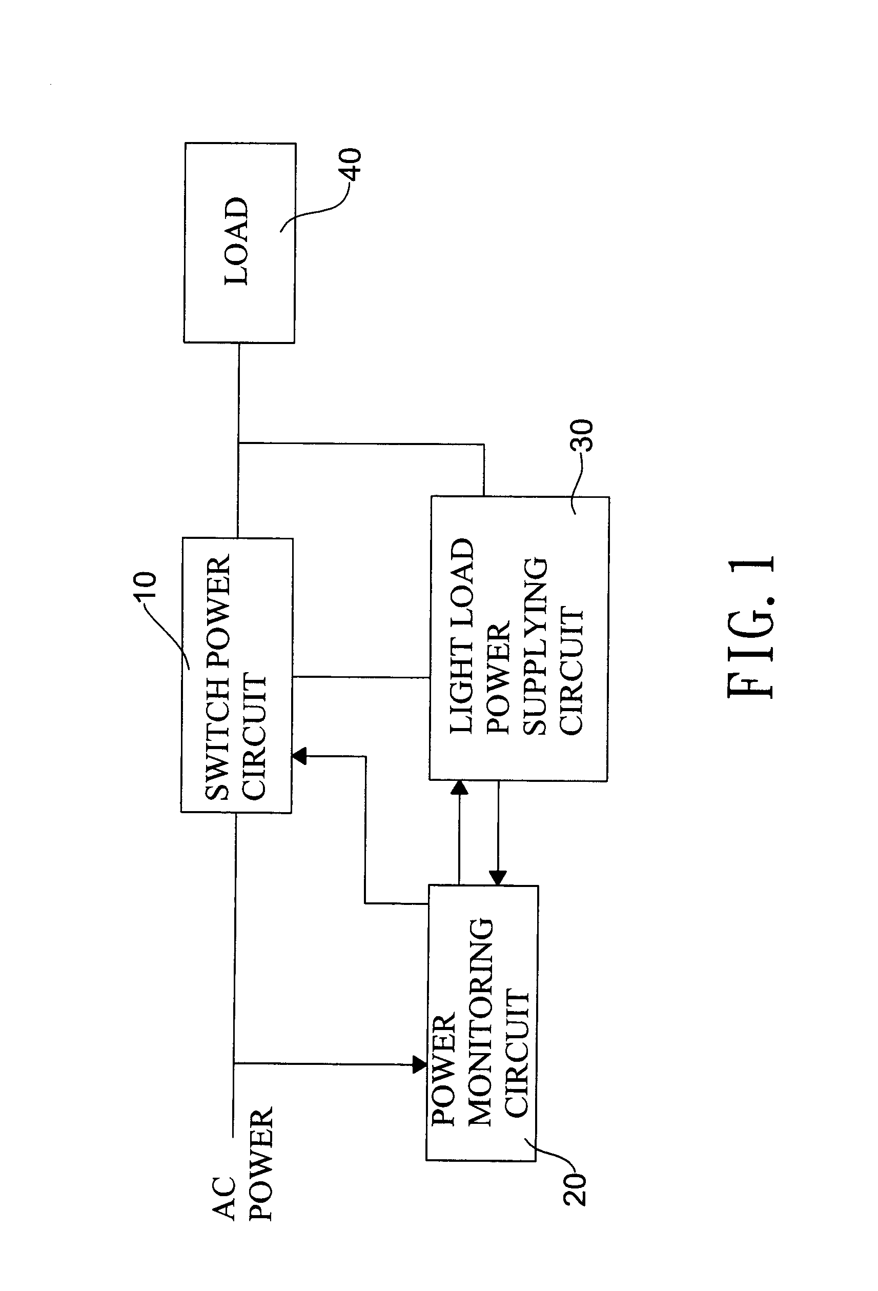
[0022]With reference to FIG. 1, a switching power circuit 10 is operated with a power monitoring circuit 20 and a light load power supplying circuit 30.

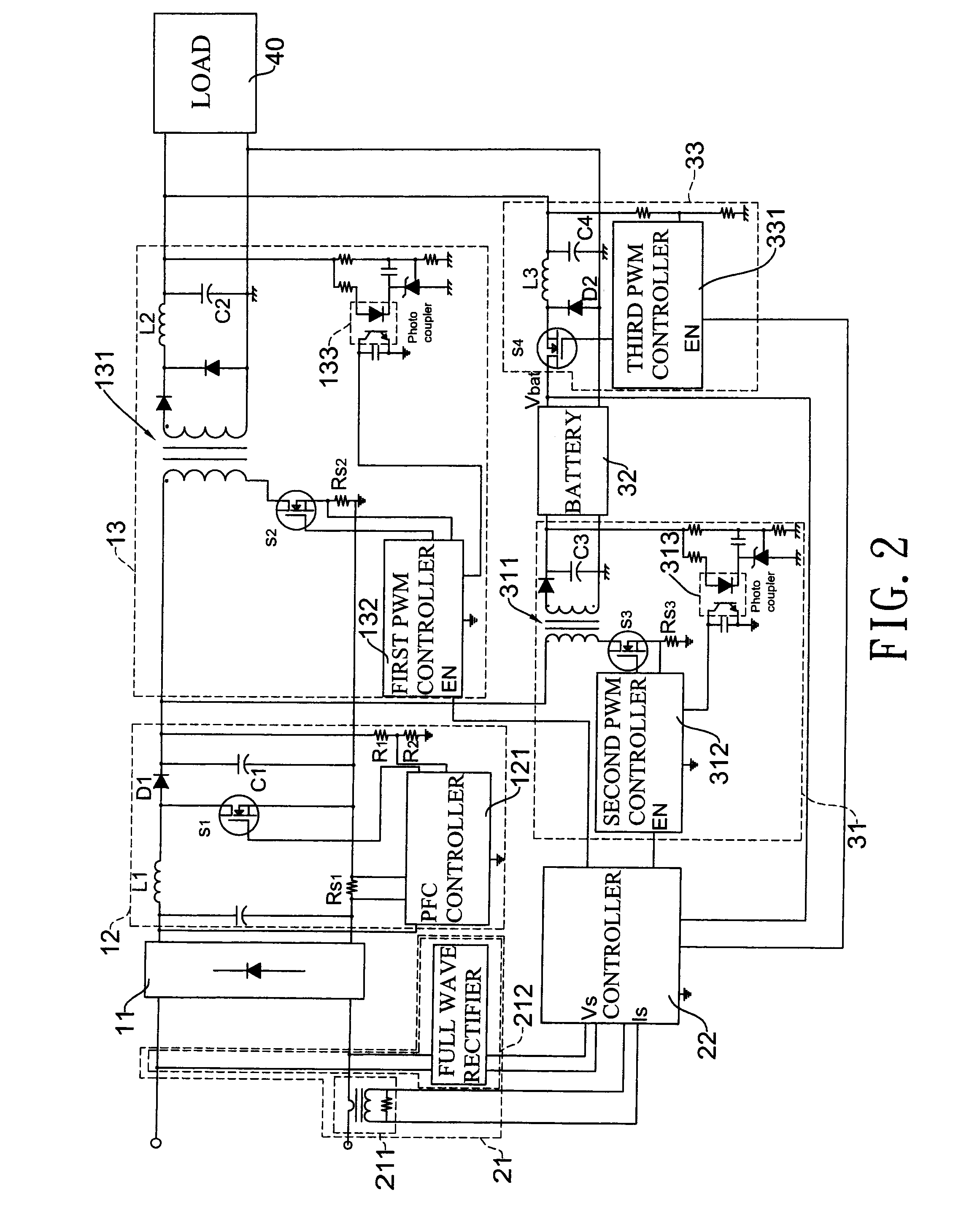
[0023]With reference to FIG. 2, the switching power circuit 10 comprises a rectifying unit 11, a power factor correction (PFC) unit 12 and a first DC to DC converter 13.

[0024]The rectifying unit 11 connects to an AC power (e.g., line voltage) and rectifies the AC power. In this embodiment, the rectifying unit 11 is a full-wave rectifier.

[0025]The PFC unit 12 connects to the rectifying unit 11 to perform power factor corrections and output high-voltage DC power. In this embodiment, the PFC unit 12 comprises an inductor L1, a diode D1, a filter capacitor C1, a first active switch S1 and a PFC controller 121. The PFC unit 12 uses the PFC controller 121 to control the conduction time of the first active switch S1, thereby changing the voltage level of the DC power output by the PFC unit 12. The PFC controller 121 connects to the filter c...


PUM


Abstract

A switching power supply with the increased efficiency at light load has a switching power circuit, a power monitoring circuit and a light load power supplying circuit. The switching power circuit converts an AC power to a stable DC power and sends the DC power to a load according to voltage variation of the load. When the power monitoring circuit detects the AC power and determines that the load is in a light state, the power monitoring circuit controls the light load power supplying circuit to output a small-power DC to the load. As the DC power provided by the light load power supplying circuit is small, the switching loss ratio is lower in its light load state. Therefore, the operating efficiency at the light load state is higher.

Description

[0001]This application claims the benefit of Taiwan Application No. 097118463, filed May 20, 2008.BACKGROUND OF THE INVENTION[0002]1. Field of the Invention[0003]The invention relates to a switching power supply and, in particular, to a switching power supply having increased power conversion efficiency at light load.[0004]2. Description of Related Art[0005]Since the line voltage is AC power while the operating power for computer devices is DC power, a power supply for converting the AC power to DC power is required for most computers.[0006]With reference to FIG. 6, a conventional power supply includes an AC to DC converting unit 81 and a DC to DC converter 82. The AC to DC converter 81 electrically connects to the line voltage to obtain the AC power and converts the AC power into a DC power. The DC to DC converter 82 electrically connects to the AC to DC converter to receive the outputted DC power and further converts the received DC power into a DC power for supplying to a load 90...

Claims


Application Information

Patent Timeline
Patent Type & Authority Applications(United States)
IPC IPC(8): H02M3/335
CPCH02M2001/007H02M3/33507H02M1/007
Inventor WHEELER, WILLIAM R.LIN, WEI-LIANG
Owner ACBEL POLYTECH INC
Learn More