Machine tool with numerical controller and on-machine measuring device

a technology of numerical controller and measuring device, which is applied in the direction of adaptive control, total factory control, instruments, etc., can solve the problems of difficult synchronization of the signal from the measuring device, high cost of signal branching device for branching the signal from the position detector, etc., and achieve the effect of reducing the shape error

Active Publication Date: 2009-11-26
FANUC LTD
View PDF6 Cites 27 Cited by
  • Summary
  • Abstract
  • Description
  • Claims
  • Application Information

AI Technical Summary

Benefits of technology

[0020]In a machine tool with a numerical controller and an on-machine measuring device according to a second aspect of the present invention, moreover, the machine tool is fitted with a position detector for detecting a position of a moving axis of the machine tool and the on-machine measuring device for measurement on the machine tool, and the numerical controller receives an axial position detection signal output from the position detector and a measurement signal output from the on-machine measuring device through interfaces. Further, these interface are designed so that the numerical controller receives the axial position detection signal and the measurement signal with the same timing. Furthermore, the numerical controller includes storage means which stores data on the axial position detection signal and the measurement signal received individually through the interfaces. The machine tool further includes shape analysis means wh...

Problems solved by technology

In this case, however, it is difficult to fetch the signal from the measuring device in synchronism with the signals from the moving axes of the machine tool into the personal computer.
However, the signal branching devices for branching the signals from the position detectors are very expensive.
Also, the signal branching requires dedicated position detector substrates and more cables for them, so that complicated wire arrangement is essential.
Further, the signals from the position detectors for the moving axes of the machine tool involve pitch errors that ar...

Method used


Image

  • Machine tool with numerical controller and on-machine measuring device
  • Machine tool with numerical controller and on-machine measuring device
  • Machine tool with numerical controller and on-machine measuring device

Examples


Embodiment Construction

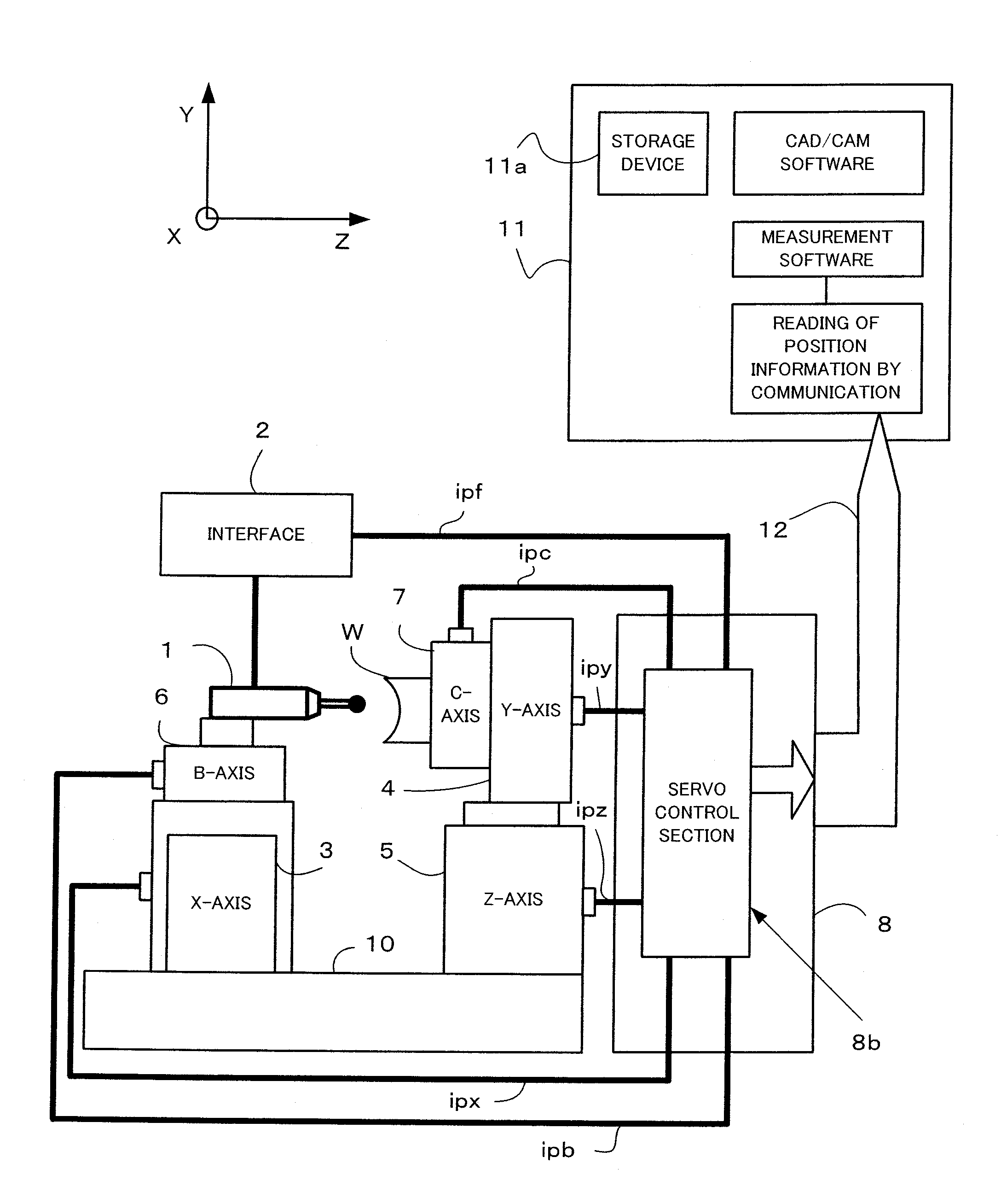
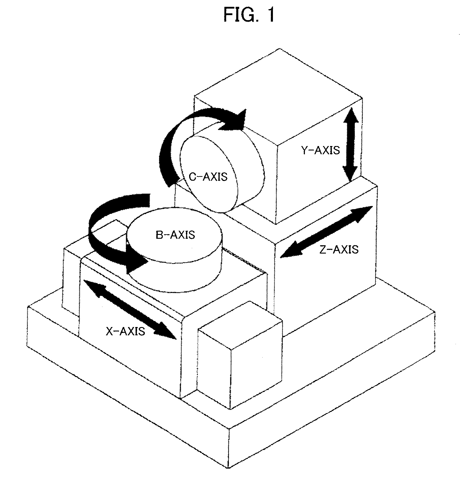
[0033]FIG. 1 shows an example of a machine tool of which moving axes include linear-drive axes and rotary axes and which is controlled by a numerical controller. This machine tool is a five-axis machine tool that has the linear-drive axes, including X-, Y- and Z-axes, and the rotary axes, including B- and C-axes. The B- and C-axes are disposed on the X- and Y-axes, respectively.

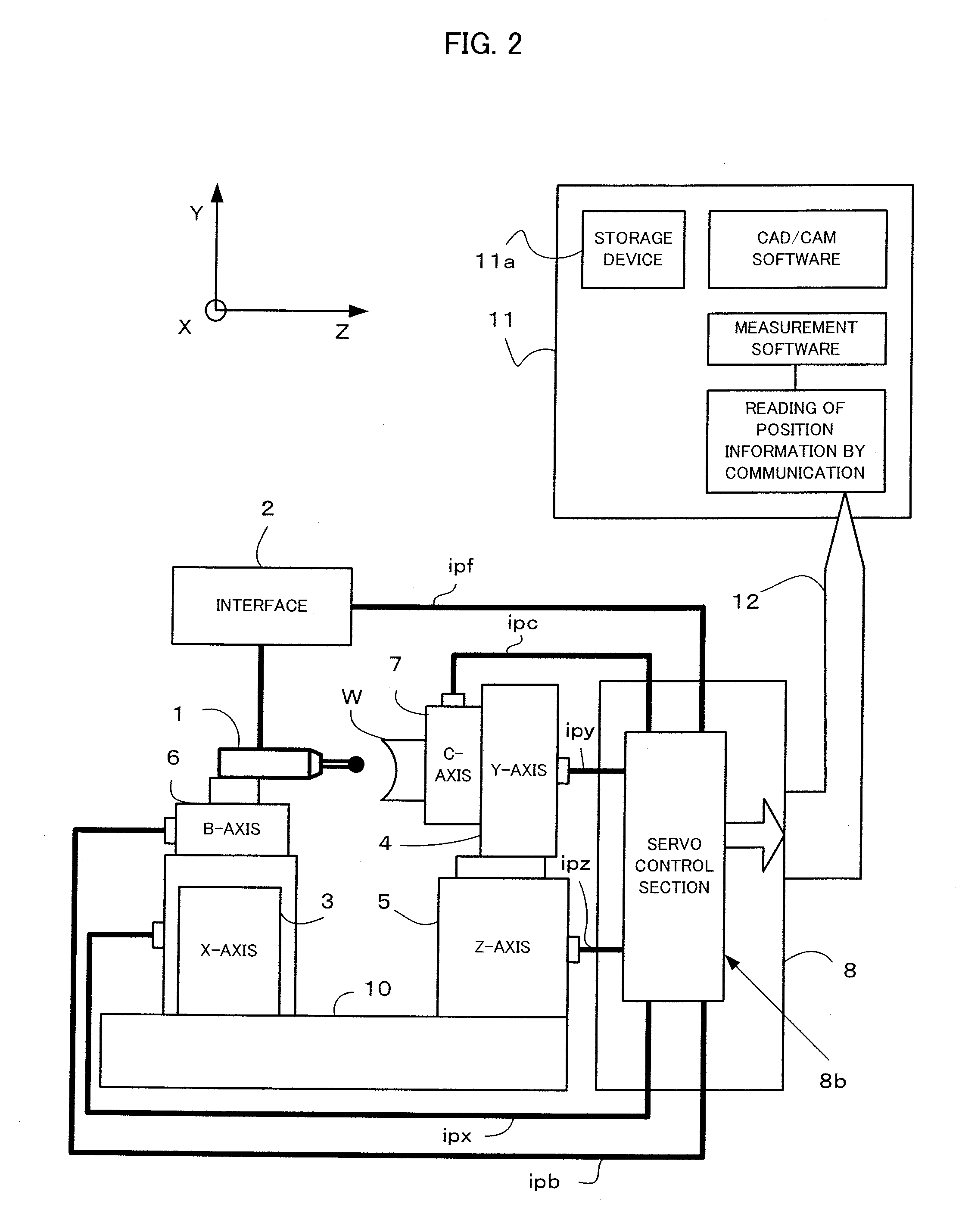
[0034]FIG. 2 is a schematic block diagram for illustrating how an on-machine measuring device 1 is mounted on the machine tool shown in FIG. 1 and used to make a measurement on the machine tool. The on-machine measuring device 1 will be described later with reference to FIG. 5.

[0035]Axial position detection signals ipx, ipy, ipz, ipb and ipc output from position detectors (not shown) that are incorporated in servomotors (not shown) for individually driving the five moving axes (X-axis 3, Y-axis 4, Z-axis 5, B-axis 6, and C-axis 7) of the machine tool are fed back through an interface (not shown) to a servo co...


PUM


Abstract

A machine tool is fitted with a position detector for detecting a position of a moving axis of the machine tool and an on-machine measuring device for measurement on the machine tool. An axial position detection signal output from the position detector and a measurement signal output from the on-machine measuring device are received through interfaces by a numerical controller that controls the machine tool. These interfaces are designed so that the numerical controller receives the axial position detection signal and the measurement signal with the same timing.

Description

BACKGROUND OF THE INVENTION[0001]1. Field of the Invention[0002]The present invention relates to a combination of a machine tool, a numerical controller for controlling the machine tool, and an on-machine measuring device mounted on the machine tool and configured to make a measurement on the machine tool.[0003]2. Description of the Related Art[0004]For high-precision machining, it is very important to measure the three-dimensional shape of a workpiece on a machine tool. Conventionally, a probe-type shape measurement sensor is known to be used to measure the shape of a workpiece in such a manner that the tip of a shape probe is brought into contact with the workpiece as the three-dimensional shape of the workpiece is measured.[0005]Japanese Patent Application Laid-Open No. 2006-21277 discloses an example of a technique in which a workpiece is measured on a machine tool that carries a shape measurer (on-machine measuring device) thereon. According to the technique disclosed in this p...

Claims


Application Information

Patent Timeline
IPC IPC(8): B23Q17/20
CPCG01B5/008B23Q17/22Y02P90/02
Inventor HON, YONPYOEBIHARA, KENZOYAMAMOTO, AKIRAHAMURA, MASAYUKI
Owner FANUC LTD
Why Eureka
Try Eureka