Method of controlling arc welding

a technology of arc welding and control method, which is applied in the direction of welding/cutting media/materials, welding apparatus, manufacturing tools, etc., can solve the problems of arcs in a state of instability, risk of poor welding, and one arc not being able to help giving influence to the other arc, etc., and achieves stable control of welding

Inactive Publication Date: 2009-12-03
PANASONIC CORP
View PDF12 Cites 13 Cited by
  • Summary
  • Abstract
  • Description
  • Claims
  • Application Information

AI Technical Summary

Benefits of technology

[0015]In a tandem arc welding system, the present method of controlling arc welding carries out the shifting of operation speed continuously and mildly. By so doing, a sharp change in the speed of weld wire supply, which is made in an effort to try to comply with change of operation speed, can be moderated. As the results, it implements a stable control of welding.

Problems solved by technology

In the tandem arc welding, where two arcs are generated in proximity, one arc can not help giving influence to the other arc.
At the welding start section and at the welding end section, among other sections, the arcs are in transient stage and cause interference to each other.
This readily brings the arcs into a state of instability, which calls for an appropriate control on them.
At the welding start section, there is a risk of poor welding, a damage on the tip due to interruption or turbulence of arching, a sputtering, etc.
However, the conventional methods of preventing mutual interference between the two arcs do not function satisfactorily for stabilizing the arcs in the high-speed welding.
Furthermore, in a high-speed welding, a change of welding speed brings the state of molten metal pool 207 into instability.
As the results, the arc becomes to be instable, which quite often makes it difficult to accomplish a consistent welding.
This causes the drawback.
In the high-speed operation, the weld wire supply needs to be increased accordingly; abrupt increase of the supply ill-affects a balance established between the supply and the melting.
This can be another cause of the inconvenience.
On the other hand, when ending a high-speed welding, the molten metal pool is disturbed by a sudden braking.

Method used


Image

  • Method of controlling arc welding
  • Method of controlling arc welding
  • Method of controlling arc welding

Examples


first exemplary embodiment

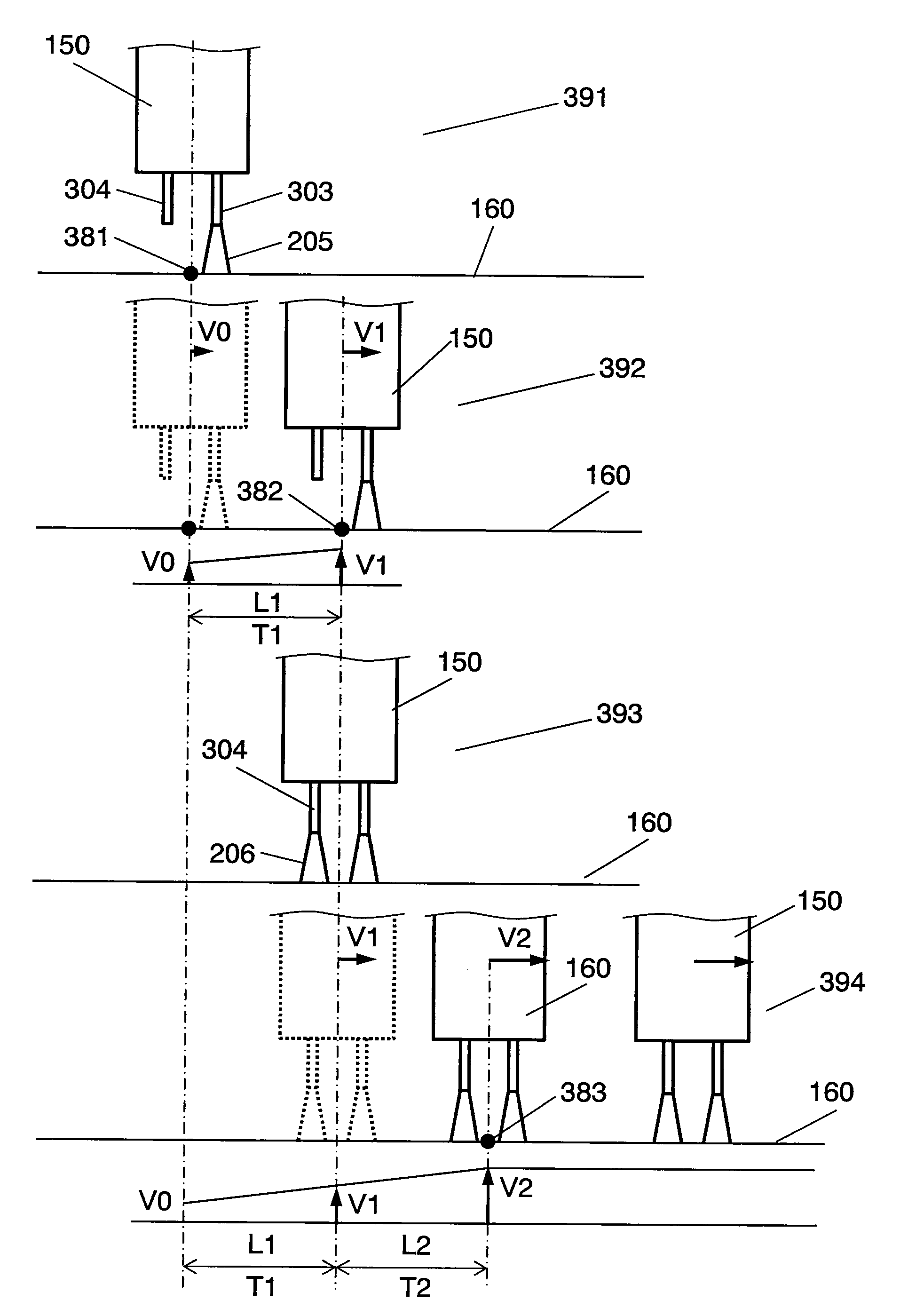
[0068]FIG. 3 shows the sequence and the contents of a welding operation carried out in accordance with first embodiment of the present invention using a tandem arc welding system mounted with integrated 2-electrode welding torch 150 (shown in FIG. 1). Operation of the present welding system proceeds in the order as shown in FIG. 3, starting from state 391 to state 392, state 393 and state 394.

[0069]In state 391, as soon as integrated 2-electrode welding torch 150 arrives at welding start point 381, it starts generating fore-going arc 205 between fore-going electrode 303 and welding object 160, and then starts traveling along the welding direction (from the left to the right, in FIG. 3). Traveling of welding torch 150 begins from welding start point381 at initial speed V0. Fore-going electrode 303 designates with fore-going electrode tip 201 and fore-going weld wire 203 included.

[0070]State 392 shows the state when welding torch 150 arrived at first point of welding start section 382...

second exemplary embodiment

[0076]Those portions in second embodiment identical to those of first embodiment are designated using the same symbols, and detailed description on which portion is eliminated. Second embodiment relates to the ending of a welding operation.

[0077]FIG. 4 shows the sequence and the contents of a welding operation carried out by a tandem arc welding system which uses integrated 2-electrode welding torch 150 (ref. FIG. 150). Actions in accordance with second embodiment proceeds in the order, starting from state 491 in FIG. 4, state 492 to state 493.

[0078]In state 491 of FIG. 4, fore-going arc 205 is terminated when integrated 2-electrode welding torch 150, which has been traveling along the welding direction (from the left to the right in FIG. 4) at speed V, arrives at first point of welding end section 481 which locates before second point of welding end section 482. Hind-going arc 206 is kept on arcing as before. First point of welding end section 481 is specified in terms of a locatio...

third exemplary embodiment

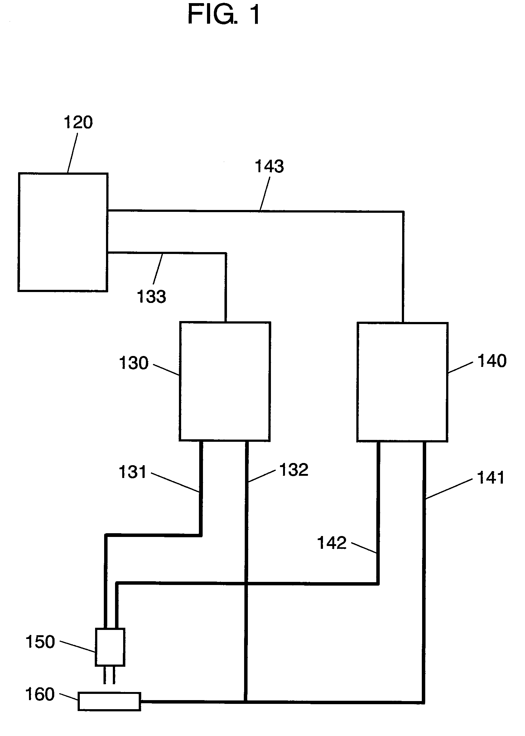
[0082]A third embodiment is described below. FIG. 5 illustrates a welding operation in the present invention on generally used welding systems, not limited to a tandem arc welding system. Exemplified in FIG. 5 is not a 2-electrode torch, but it is welding torch 550 having a single electrode. Welding torch 550 is a counterpart to welding torch 150 of FIG. 1. In the present third embodiment, however, welder 140, grounding cable 141, power cable 142 and control line 143 are not needed.

[0083]In FIG. 5, arcing torch 550 which has been traveling in the welding direction (from the left to the right in FIG. 5) shifts the traveling speed gradually so as it becomes Va at first point 581, and Vb at second point 582. Second point 582 is specified in terms of a location, a distance L5 from first point 581 or a time span T5 from first point 581. While welding torch 550 is traveling from first point 581 to second point 582, control unit 120 (ref. FIG. 1) sends at first point 581 such welding condi...


PUM

PropertyMeasurementUnit
speedaaaaaaaaaa
travel speedaaaaaaaaaa
voltageaaaaaaaaaa

Abstract

A method of controlling arc welding, which method shifting the speed of welding operation continuously and mildly. By so doing, a sharp change in the speed of weld wire supply, which is caused as the result of efforts to try to comply with an abrupt change in operation speed, can be moderated. This helps keeping a welding operation under a stable control.

Description

FIELD OF THE INVENTION[0001]The present invention relates to a method of controlling welding operation performed by an arc welding device mounted on a welding robot manipulator or the like facility.BACKGROUND OF THE INVENTION[0002]At the welding lines in manufacturing firms, efforts are being made to improve the total operating efficiency by increasing the speed of welding operation. An increasing number of firms are trying to introduce a high-speed welding. Aiming to secure molten weld metals for enough volume in high-speed welding, some wire feeders capable of supplying weld wire for a sufficient amount are already made available.[0003]Meanwhile, a tandem arc welding process has also been introduced as a means of increasing the speed of welding taking advantage of the technology of the above high-capacity wire feeders. In a tandem arc welding system, an integrated 2-electrode welding torch or two single-electrode welding torches disposed separated to each other by a certain specif...

Claims


Application Information

Patent Timeline
Patent Type & Authority Applications(United States)
IPC IPC(8): B23K9/00
CPCB23K9/067B23K9/1735B23K9/121B23K9/095
Inventor YOSHIMA, KAZUMASA
Owner PANASONIC CORP
Why Eureka
Try Eureka