Liquid crystal display device

a liquid crystal display and display device technology, applied in the field of liquid crystal display devices, can solve the problems of severe vertical crosstalk, large amount of parts and time, and the inability to manufacture a slim liquid crystal display device, so as to improve touch sensitivity and prevent crosstalk.

Active Publication Date: 2009-12-03
LG DISPLAY CO LTD
View PDF5 Cites 46 Cited by
  • Summary
  • Abstract
  • Description
  • Claims
  • Application Information

AI Technical Summary

Benefits of technology

[0039]An object of the present invention is to provide a liquid crystal display device having optical sensors embedded in a liquid crystal panel to sense a touch and capable of preventing crosstalk by changing positions of read-out lines to improve touch sensitivity and a method for manufacturing the same.

Problems solved by technology

The vertical crosstalk is one of factors causing a malfunction in application of a touch algorithm.
The conventional liquid crystal display device has the following problems.
When optical sensors are provided externally, it is impossible to manufacture a slim liquid crystal display device.
In attachment of parts for connecting optical sensors to an internal liquid crystal panel, a large amount of parts and time are required.
Thus, severe vertical crosstalk occurs at these positions due to generation of parasitic capacitance.
Further, the parasitic capacitance also influences the blue pixel regions at which the optical sensors are positioned.
Further, the amount of charges increases in the capacitors included in the optical sensors due to sensing of touch and the charges are transmitted to the storage voltage lines, thereby causing horizontal crosstalk due to distortion of a phase voltage applied to storage voltage lines.

Method used


Image

  • Liquid crystal display device
  • Liquid crystal display device
  • Liquid crystal display device

Examples


second embodiment

[0099]FIG. 7 illustrates a circuit diagram showing the liquid crystal display device according to the present invention.

[0100]In the second embodiment of FIG. 7, a first sensing portion 510 for sensing a touch is formed at a red pixel, and a second sensing portion 511 for sensing a next touch is formed at a green pixel.

[0101]According to the second embodiment, the touch sensing portions are alternately formed at red, green and blue pixel regions. When three red, green and blue pixel regions are defined as one pixel and the touch sensing portion is formed for each of four pixels, the next sensing portion is formed at the next pixel region at the corresponding pixel. For example, when the touch sensing portion is formed for each of four pixels, the sensing portion is provided for each of thirteen pixel regions. That is, the sensor is positioned at the pixel region (sub-pixel) of the next color after skipping four pixels. Accordingly, when one sensor is positioned for each of thirteen ...

third embodiment

[0109]FIG. 8 illustrates a circuit diagram showing a liquid crystal display device according to the present invention.

[0110]As shown in FIG. 8, the liquid crystal display device according to the third embodiment of the present invention includes a first substrate (not shown) and a second substrate (not shown) facing each other to include a plurality of pixel regions spaced from each other, and a liquid crystal layer (not shown) filled between the first and second substrates.

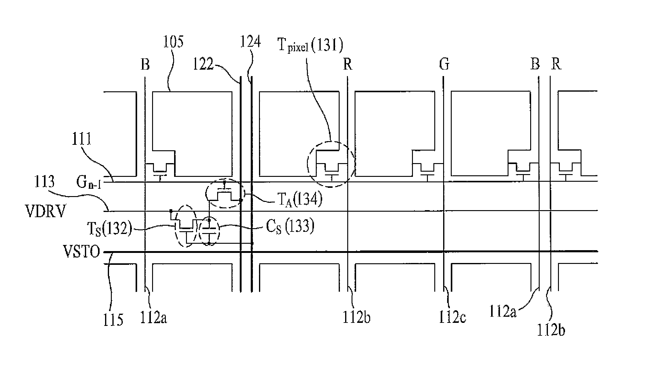
[0111]The first substrate includes gate lines 311 formed to separate the pixel regions in a first direction, driving voltage lines 313 and first storage lines 315 parallel to the gate lines 311 and spaced from each other, data lines 312a, 312b and 312c formed between the pixel regions in a second direction intersecting the first direction, read-out lines 322, display transistors (Tpixel) 331 formed at intersecting portions of the gate lines 311 and the data lines 312a, 312b and 312c, pixel electrodes 305 formed i...


PUM


Abstract

A liquid crystal display device having optical sensors, for sensing a touch, embedded in a liquid crystal panel to improve touch sensitivity is disclosed. The liquid crystal display device includes pixel regions spaced from each other on a first substrate, gate lines formed to separate the pixel regions in a first direction, driving voltage lines parallel to the gate lines, data lines formed between the pixel regions in a second direction intersecting the first direction, storage lines parallel to the driving voltage lines, read-out lines separated from neighboring data lines by one pixel region in the second direction, display transistors formed at intersections of the gate and data lines, pixel electrodes formed in the pixel regions, output switching transistors formed between the gate and read-out lines, capacitors formed between the output switching transistors and storage lines, and photo sensing transistors formed on the output switching transistors and storage lines.

Description

CROSS-REFERENCE TO RELATED APPLICATION[0001]This application claims the benefit of Korean Patent Application No. 10-2008-0049074, filed on May 27, 2008, which is hereby incorporated by reference in its entirety as if fully set forth herein.BACKGROUND OF THE INVENTION[0002]1. Field of the Invention[0003]The present invention relates to a liquid crystal display device, and more particularly to a liquid crystal display device having optical sensors embedded in a liquid crystal panel to sense a touch and capable of preventing crosstalk by changing positions of read-out lines to improve touch sensitivity and a method for manufacturing the same.[0004]2. Discussion of the Related Art[0005]As an information-oriented society has been developed, a display field has been rapidly developed to visually express electrical data signals, and various flat display devices having excellent performances, such as thin profile, light weight, and low power consumption, have been developed and rapidly repl...

Claims


Application Information

Patent Timeline
Patent Type & Authority Applications(United States)
IPC IPC(8): G09G3/36
CPCG02F1/13338G02F1/1362G06F3/042G06F3/0412G02F2001/13312G02F1/13312G09G3/36
Inventor LEE, KYUNG EONYU, SANG HEEYU, JAE SUNGLEE, DEUK SULEE, BU YEOL
Owner LG DISPLAY CO LTD
Why Eureka
Try Eureka