Thin-film magnetic head, method of manufacturing the same, head gimbal assembly, and hard disk drive

Active Publication Date: 2009-12-03
HEADWAY TECH INC +1
View PDF10 Cites 54 Cited by
  • Summary
  • Abstract
  • Description
  • Claims
  • Application Information

AI Technical Summary

Benefits of technology

[0011]However, the thin-film coils 404, 414 generate heat when a current flows therethrough. In the case of the thin-film coil 404, for example, a photoresist layer 405 is arranged about the turn parts 403a, 403b, 403c, 403d, whereby the heat generated by the thin-film coil 404 is transmitted to the photoresist layer 405 thereabout. The photoresist layer 405 is formed from an organic material and thus has a coefficient of expansion greater than that of the thin-film coil 404. Therefore, the photoresist layer 405 is easier to expand when heated. When the photoresist layer 405 expands, the end part of the write shield layer on the ABS 401 side is pushed out, whereby the end part of the lower shield layer 406 on the ABS 401 side projects.
[0012]For enhancing magnetic fields generated by the thin-film coils 404, 410, it is desirable to increase the number of turn parts (number of turns) as much as possible. For increasing the number of turns while keeping the length (hereinafter referred to as “yoke length”) from the medium-opposing surface 401 of the main magnetic pole layer to the write shield layer 402, the widths of the turn parts 403a, 403b, 403c, 403d may be narrowed in the case of the thin-film coil 404. However, this makes it harder for the current to flow through the turn parts 403a, 403b, 403c, 403d, which raises the resistance value

Problems solved by technology

This will increase the magnetic path length, however.
These characteristics are harder to improve when the magnetic path length is longer.
Ther

Method used


Image

  • Thin-film magnetic head, method of manufacturing the same, head gimbal assembly, and hard disk drive
  • Thin-film magnetic head, method of manufacturing the same, head gimbal assembly, and hard disk drive
  • Thin-film magnetic head, method of manufacturing the same, head gimbal assembly, and hard disk drive

Examples


first embodiment

[0074]Structure of Thin-Film Magnetic Head

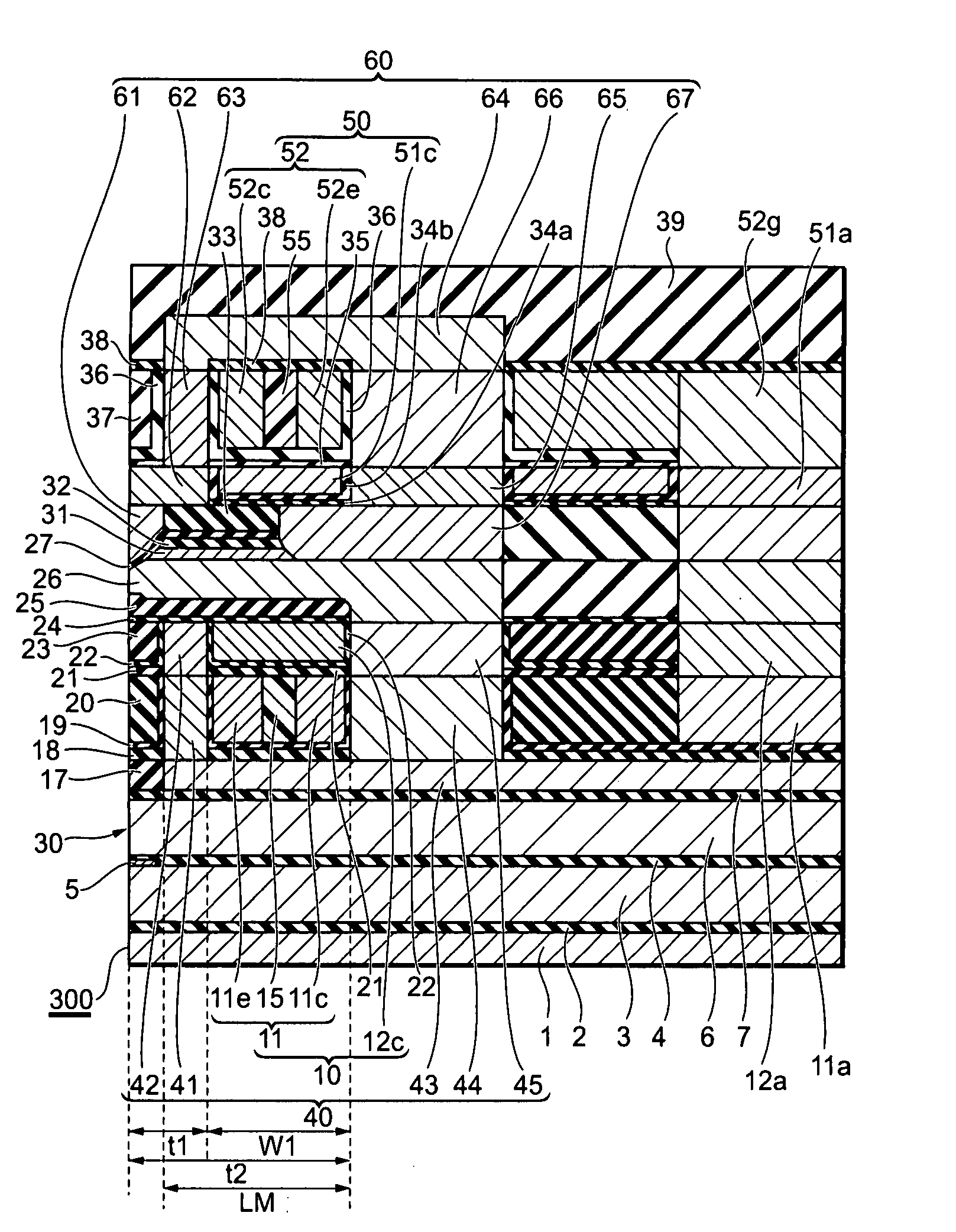
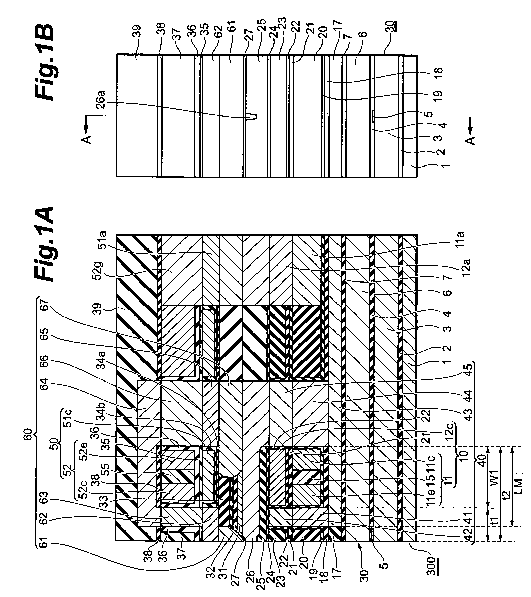
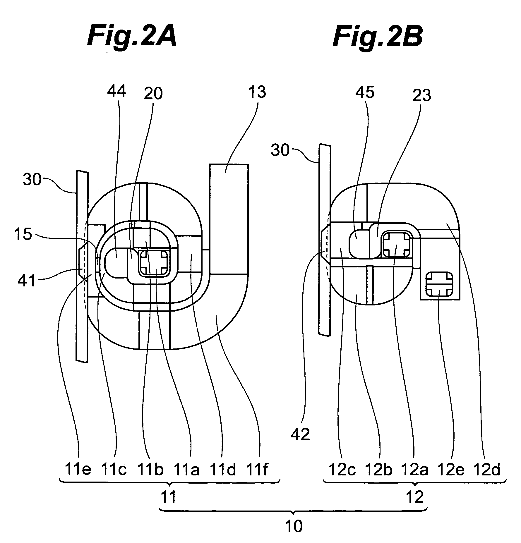
[0075]To begin with, the structure of a thin-film magnetic head of perpendicular magnetic recording type in accordance with the first embodiment of the present invention will be explained with reference to FIGS. 1A and 1B to 4A and 4B. Here, FIG. 1A is a sectional view of the thin-film magnetic head 300 in accordance with the first embodiment of the present invention taken along the line A-A of FIG. 1B, which is a direction intersecting its air bearing surface (which will hereinafter be referred to as ABS), while FIG. 1B is a front view showing the ABS 30 of the thin-film magnetic head 300. FIG. 2A is a plan view showing a first conductor layer 11 and a first rear shield part 44, while FIG. 2B is a plan view showing a second conductor layer 12 and a second rear shield part 45. FIG. 3A is a plan view showing a main part of the first conductor layer 11, while FIG. 3B is a plan view showing a main part of the second conductor layer 12. FIG. 4A ...

second embodiment

[0165]The structure of a thin-film magnetic head of perpendicular magnetic recording type in accordance with the second embodiment of the present invention will now be explained with reference to FIG. 21. FIG. 21 is a sectional view, corresponding to FIG. 1A, of the thin-film magnetic head 310 in accordance with the second embodiment of the present invention taken along a direction intersecting the ABS 30.

[0166]As with the thin-film magnetic head 300, the thin-film magnetic head 310 comprises a substrate 1 and reproducing and recording heads laminated on the substrate 1, while having the ABS 30. Since the thin-film magnetic head 310 includes configurations identical to those of the thin-film magnetic head 300, configurations of the thin-film magnetic head 310 different from those of the thin-film magnetic head 300 will mainly be explained in the following, while omitting or simplifying their common configurations.

[0167]As in the thin-film magnetic head 300, the reproducing head incl...

third embodiment

[0178]The structure of a thin-film magnetic head of perpendicular magnetic recording type in accordance with the third embodiment of the present invention will now be explained with reference to FIG. 22. FIG. 22 is a sectional view, corresponding to FIG. 1A, of the thin-film magnetic head 320 in accordance with the third embodiment of the present invention taken along a direction intersecting the ABS 30.

[0179]As with the thin-film magnetic head 310, the thin-film magnetic head 320 comprises a substrate 1 and reproducing and recording heads laminated on the substrate 1, while having the ABS 30. The thin-film magnetic head 320 differs from the above-mentioned thin-film magnetic head 310 only in the configuration of the recording head. In the following explanations, configurations of the thin-film magnetic head 320 different from those of the thin-film magnetic head 310 will mainly be explained, while omitting or simplifying their common configurations.

[0180]The recording head includes...


PUM


Abstract

A thin-film magnetic head is constructed such that a main magnetic pole layer having a magnetic pole end face on a side of a medium-opposing surface opposing a recording medium, a write shield layer opposing the main magnetic pole layer on the medium-opposing surface side, a gap layer formed between the main magnetic pole layer and write shield layer, and a thin-film coil wound about the write shield layer or main magnetic pole layer are laminated on a substrate. This thin-film magnetic head has an equidistant two-stage structure in which a first turn part of a first conductor layer and a second turn part of a second conductor layer overlap vertically along the medium-opposing surface while having the same front distance from respective front side faces closer to the medium-opposing surface to the medium-opposing surface.

Description

BACKGROUND[0001]1. Field of the Invention[0002]The present invention relates to a thin-film magnetic head which performs a magnetic recording action by a perpendicular recording scheme, a method of manufacturing the same, a head gimbal assembly, and a hard disk drive.[0003]2. Related Background Art[0004]In recent years, hard disk drives have remarkably been improving their areal recording density. The areal recording density of hard disks has recently reached and is about to exceed 160 to 200 GB / platter in particular. In keeping with this trend, thin-film magnetic heads have been required to improve their performances.[0005]The thin-film magnetic heads can roughly be classified according to their recording schemes into those of longitudinal magnetic recording type and those of perpendicular magnetic recording type. The longitudinal magnetic recording scheme records data in a (longitudinal) direction within a recording surface of a hard disk (recording medium), while the perpendicula...

Claims


Application Information

Patent Timeline
IPC IPC(8): G11B5/127
CPCG11B5/1278G11B5/3163G11B5/3116
Inventor SASAKI, YOSHITAKAITO, HIROYUKIIIJIMA, ATSUSHI
Owner HEADWAY TECH INC
Why Eureka
Try Eureka