Thermo-optic phase shifter and method for manufacturing same

Inactive Publication Date: 2009-12-03
NEC CORP
View PDF5 Cites 26 Cited by
  • Summary
  • Abstract
  • Description
  • Claims
  • Application Information

AI Technical Summary

Benefits of technology

[0039]As described above, with the present invention, a thermo-optic phase shifter with excellent optical characteristics can be produced easily, with good control, and at a high yield. Also, the sacrificial layer and cladding layer can be formed continuously, which greatly simplifies the production process. As a result, production costs can be reduced and yield increased. Furthermore, even though the sacrificial layer of the thermo-optic phase shifter part is removed, the sacrificial layer r

Problems solved by technology

However, if a plurality of thermo-optic phase shifters are disposed in a single optical circuit for the sake of multiplexing, powe

Method used


Image

  • Thermo-optic phase shifter and method for manufacturing same
  • Thermo-optic phase shifter and method for manufacturing same
  • Thermo-optic phase shifter and method for manufacturing same

Examples


Embodiment Construction

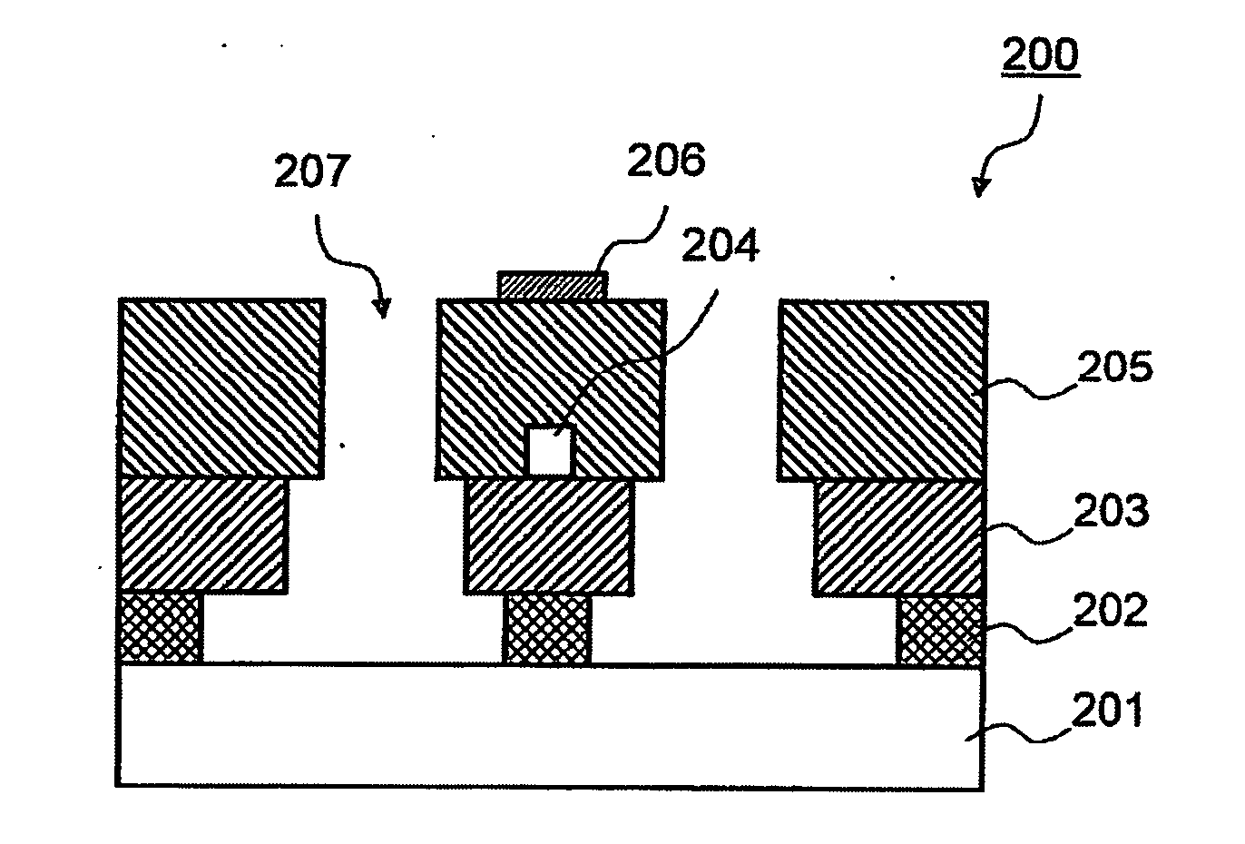
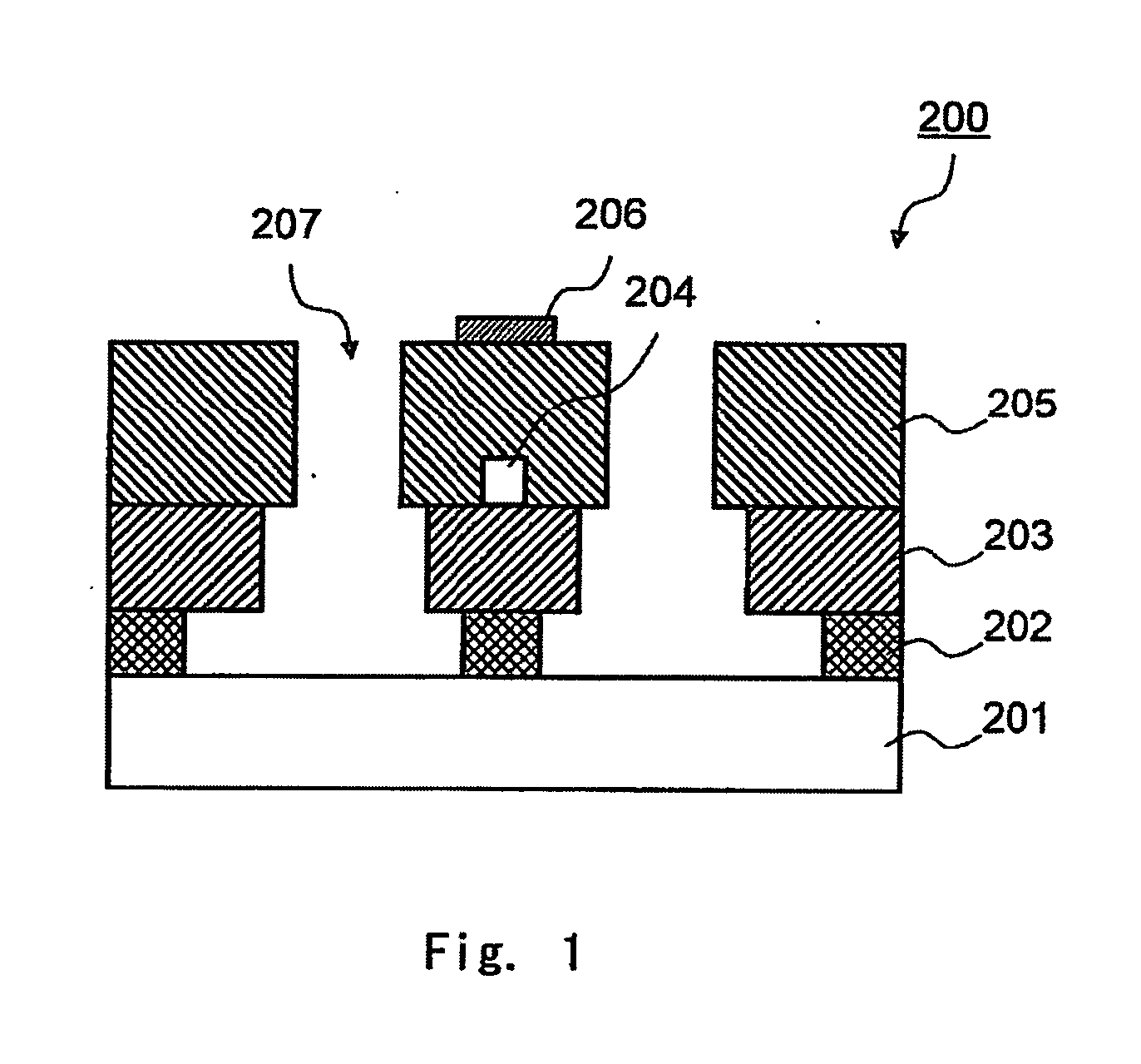
[0070]The present invention will now be described in detail on the basis of embodiments. FIG. 1 shows the cross sectional structure of the main components of the thermo-optic phase shifter in an embodiment of the present invention. The energy-efficient thermo-optic phase shifter 200 of this embodiment includes a substrate 201, a sacrificial layer 202 provided over this substrate 201, a lower cladding layer 203 formed on this sacrificial layer 202, an optical waveguide core 204 formed on the lower cladding layer 203, an upper cladding layer 205 provided so as to cover the optical waveguide core 204, and a heat-generating heater 206 provided in a region directly above the optical waveguide core 204. A characteristic features is that a heat-blocking structure is formed in which all or at least part of the sacrificial layer 202 in the region directly under the optical waveguide core 204, and the sacrificial layer 202 and the upper cladding layer 205 and lower cladding layer 203 in the s...


PUM

PropertyMeasurementUnit
Densityaaaaaaaaaa

Abstract

The thermo-optic phase shifter (200) according to an exemplary aspect of the invention includes: a substrate (201); a sacrificial layer (202) formed above the substrate (201); a first cladding layer (203) formed above the sacrificial layer (202) and having a film density higher than that of the sacrificial layer (202); an optical waveguide core (204) formed above the first cladding layer (203); a second cladding layer (205) provided over the first cladding layer (203) to cover the optical waveguide core (204); a heat-generating heater (206) provided to a region of the second cladding layer (205) directly above the optical waveguide core (204); and a groove (207) formed in a side face region of the optical waveguide core (204) and extending from the surface of the second cladding layer (205) to the surface of the substrate (201).

Description

TECHNICAL FIELD[0001]The present invention relates to a thermo-optic phase shifter and a method for manufacturing the same, and more particularly relates to a thermo-optic phase shifter that can be favorably used as an optical device such as a wavelength filter, a variable attenuator, or a switch that makes use of phase changes produced by thermo-optical effect.BACKGROUND ART[0002]In the field of optical communication, multi-channel communication is making rapid strides due to the advent of the wavelength division multiplexing (WDM) communication system. Along with this, optical elements are necessary in a quantity corresponding to the number of channels in order to achieve functional control over each channel. Examples of this are keeping the power of each channel consistent, and performing switching.[0003]Accordingly, there is a growing need for small-sized optical circuit components that can be applied to optical switches and other such optical devices. A number of single-unit op...

Claims


Application Information

Patent Timeline
IPC IPC(8): G02F1/01B05D5/06C23C16/513C23C14/34C23F1/00
CPCG02F1/0147G02F1/0113
Inventor TAKAHASHI, MORIO
Owner NEC CORP
Why Eureka
Try Eureka