Fixed Swirl Inducing Blast Liner

a technology of abrasive slurry and a blast liner, which is applied in the direction of drilling casings, drilling pipes, and accessories of wells, etc., can solve the problems of reducing erosion in exit ports and longer service life, and achieves the effects of reducing turbulence, reducing wear in abrasive slurry service, and reducing erosion

Inactive Publication Date: 2009-12-10
BAKER HUGHES INC
View PDF1 Cites 12 Cited by
  • Summary
  • Abstract
  • Description
  • Claims
  • Application Information

AI Technical Summary

Benefits of technology

[0007]Wear is reduced in abrasive slurry service at an outlet into an annular space defined by the wellbore and around the tool. In a gravel packing application with a crossover, the slurry exits a central passage and goes into an internal annulus in the tool. Turning vanes that make at least one half turn and that have a height at least partially the height of the annular spac...

Problems solved by technology

As a result of the lower turbulence leading to the final exit from the tool into th...

Method used


Image

  • Fixed Swirl Inducing Blast Liner
  • Fixed Swirl Inducing Blast Liner
  • Fixed Swirl Inducing Blast Liner

Examples


Embodiment Construction

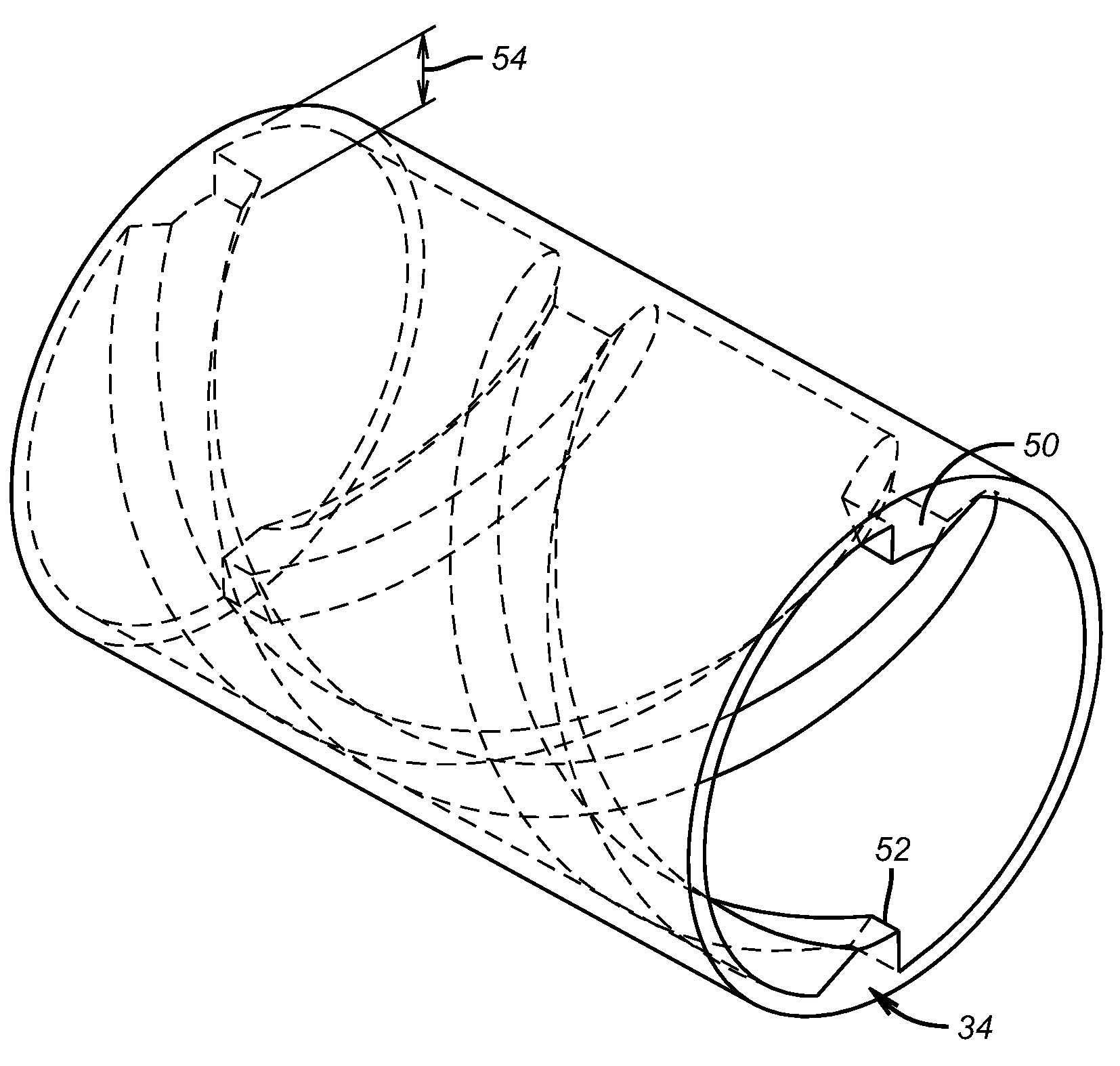
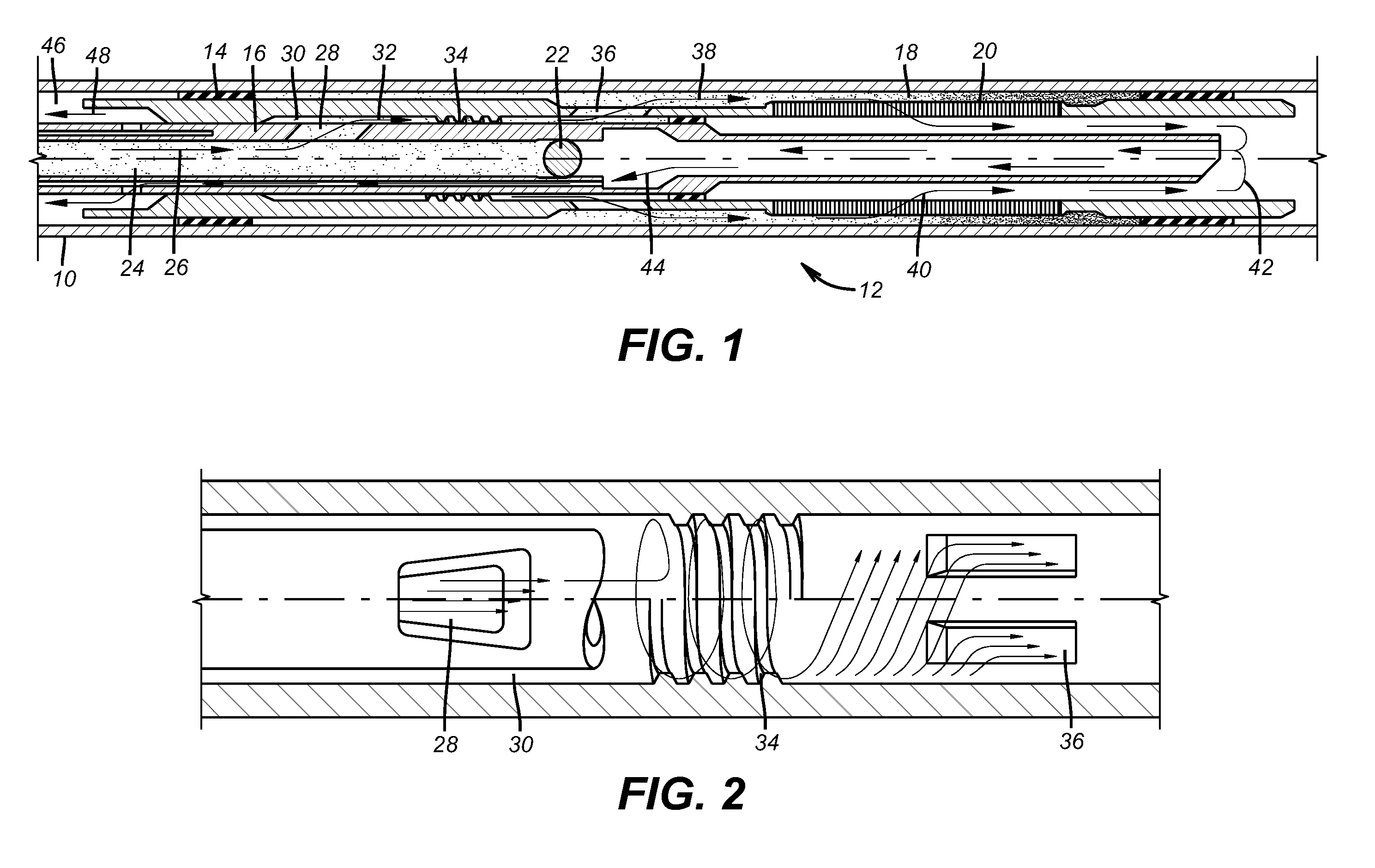
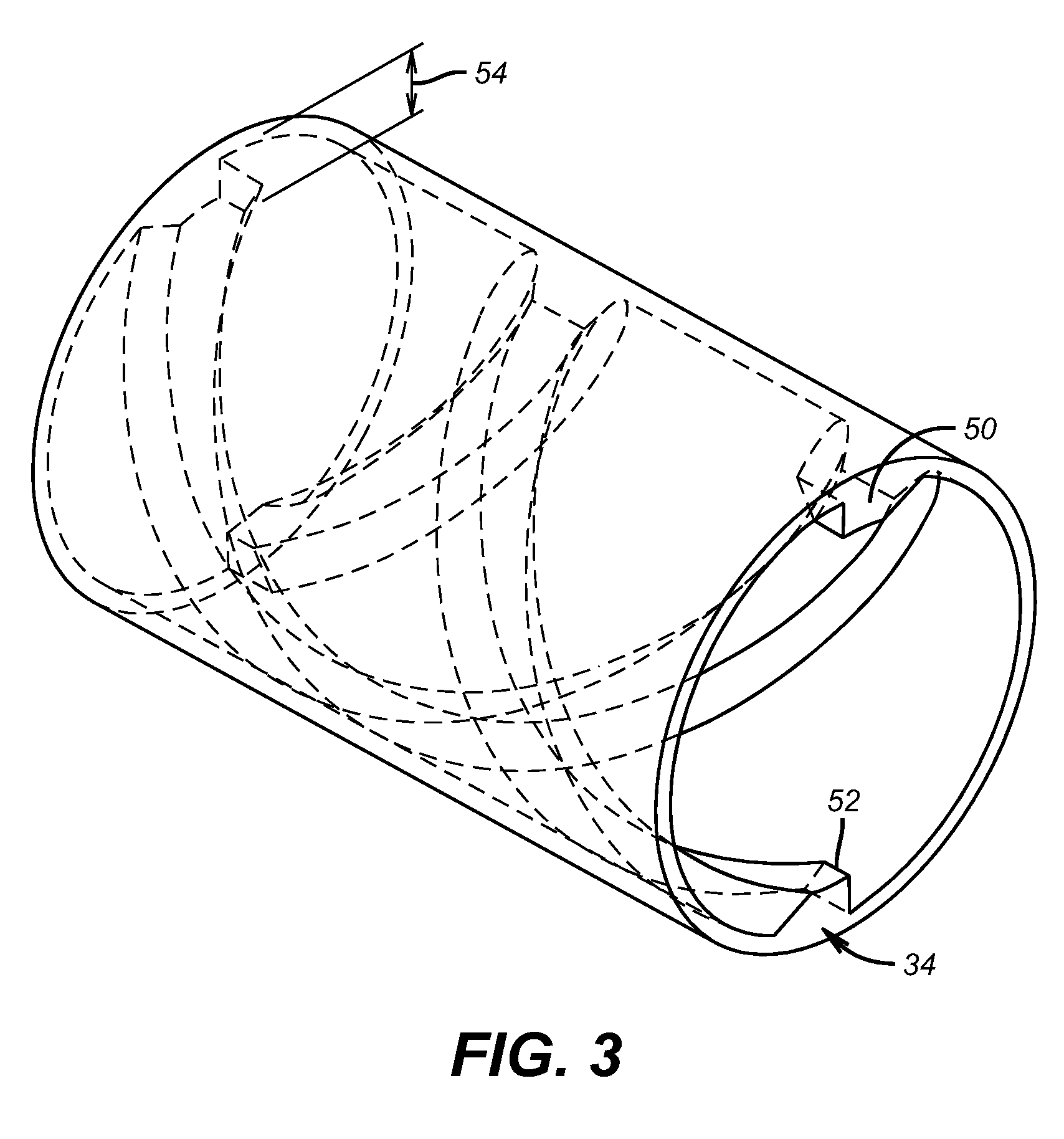
[0011]FIG. 1 shows casing 10 and a gravel packing assembly 12 located within. An external packer 14 is set against the casing 10. A crossover tool 16 is shown in a position for gravel deposition in annulus 18 around screens 20. A ball 22 has been dropped to a seated position blocking off passage 24. Arrow 26 represents slurry being pumped from the surface through passage 24. The flow exits through openings 28 into an inner annulus 30. Arrow 32 represents this flow. In annulus 30 vanes 34, best seen in detail in FIG. 3, impart a swirling motion to the slurry flow in annulus 30. The flow of slurry then exits ports 36 into annulus 18 as illustrated by arrow 38. The solids from the slurry remain in annulus 18 while the carrier fluid goes through screen 20 as represented by arrow 40. Flow continues as represented by arrows 42 and 44 to bypassing ball 22 to exit into annulus 46 above the packer 14 as indicated by arrow 48.

[0012]Focusing now on what happens between ports 28 and 36 in annul...


PUM


Abstract

Wear is reduced in abrasive slurry service at an outlet into an annular space defined by the wellbore and around the tool. In a gravel packing application with a crossover, the slurry exits a central passage and goes into an internal annulus in the tool. Turning vanes that make at least one full turn and that have a height at least partially the height of the annular space are there to impart a swirl movement to at least a portion of the slurry stream. The swirling motion has beneficial effects of reducing turbulence which allows a velocity reduction for a comparable output volume. As a result of the lower turbulence leading to the final exit from the tool into the surrounding annulus, the exit ports experience reduced erosion and longer service life.

Description

FIELD OF THE INVENTION[0001]The field of the inventions is slurry delivery devices for downhole use and more particularly features of such devices that resist wear and erosion at the delivery ports.BACKGROUND OF THE INVENTION[0002]Gravel packing and fracturing equipment involves moving a slurry flow from an internal flow bore through an internal annulus in the tool and ultimately out an exterior wall to an outer annulus usually around screens. Typically the tool that is used is a crossover that can take various positions for delivery of fracturing fluid and at another time delivery of gravel slurry with other positions that allow removal of excess fluid through circulation or reverse circulation.[0003]The gravel slurry is fairly abrasive and when combined with the flow rates that can occur in the crossover tool it often results in high wear of parts that receive an impact from the fluid stream as it changes direction within the tool. One effort to address the erosion issue within th...

Claims


Application Information

Patent Timeline
IPC IPC(8): E21B17/22
CPCE21B17/22E21B43/045E21B43/04
Inventor CLEM, NICHOLAS J.CORONADO, MARTIN P.
Owner BAKER HUGHES INC
Why Eureka
Try Eureka