Method and system for improving residual stress in tube body

Inactive Publication Date: 2009-12-10
MITSUBISHI HEAVY IND LTD
View PDF6 Cites 14 Cited by
  • Summary
  • Abstract
  • Description
  • Claims
  • Application Information

AI Technical Summary

Benefits of technology

[0028]According to the present invention, the intensity of laser irradiation is properly increased or decreased at the start and end angles of the laser irradiation at one turn of rotation. Accordingly, the tube body can be prevented from being excessively heated, and laser heating can reliably improve the residual stress (tensile stress) in the inner surface of the tube body due to welding. Moreover, the intensity of laser irradiation is properly increased and decreased at the start and end angles of laser irradiation at a plurality of cycles with the start and end angles being shifted for each cycle. It is

Problems solved by technology

In the case of laying tube bodies such as large pipes in nuclear power plants, large plants, and the like, removal of stress remaining

Method used


Image

  • Method and system for improving residual stress in tube body
  • Method and system for improving residual stress in tube body
  • Method and system for improving residual stress in tube body

Examples


embodiment 1

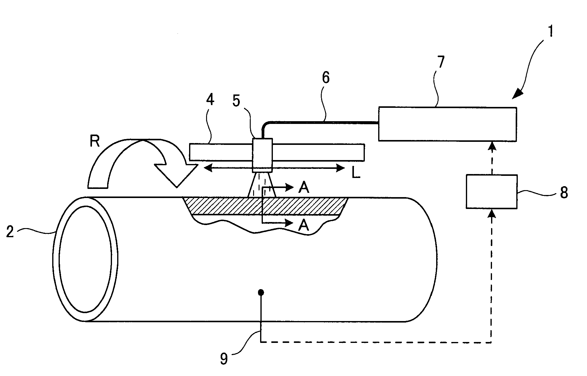
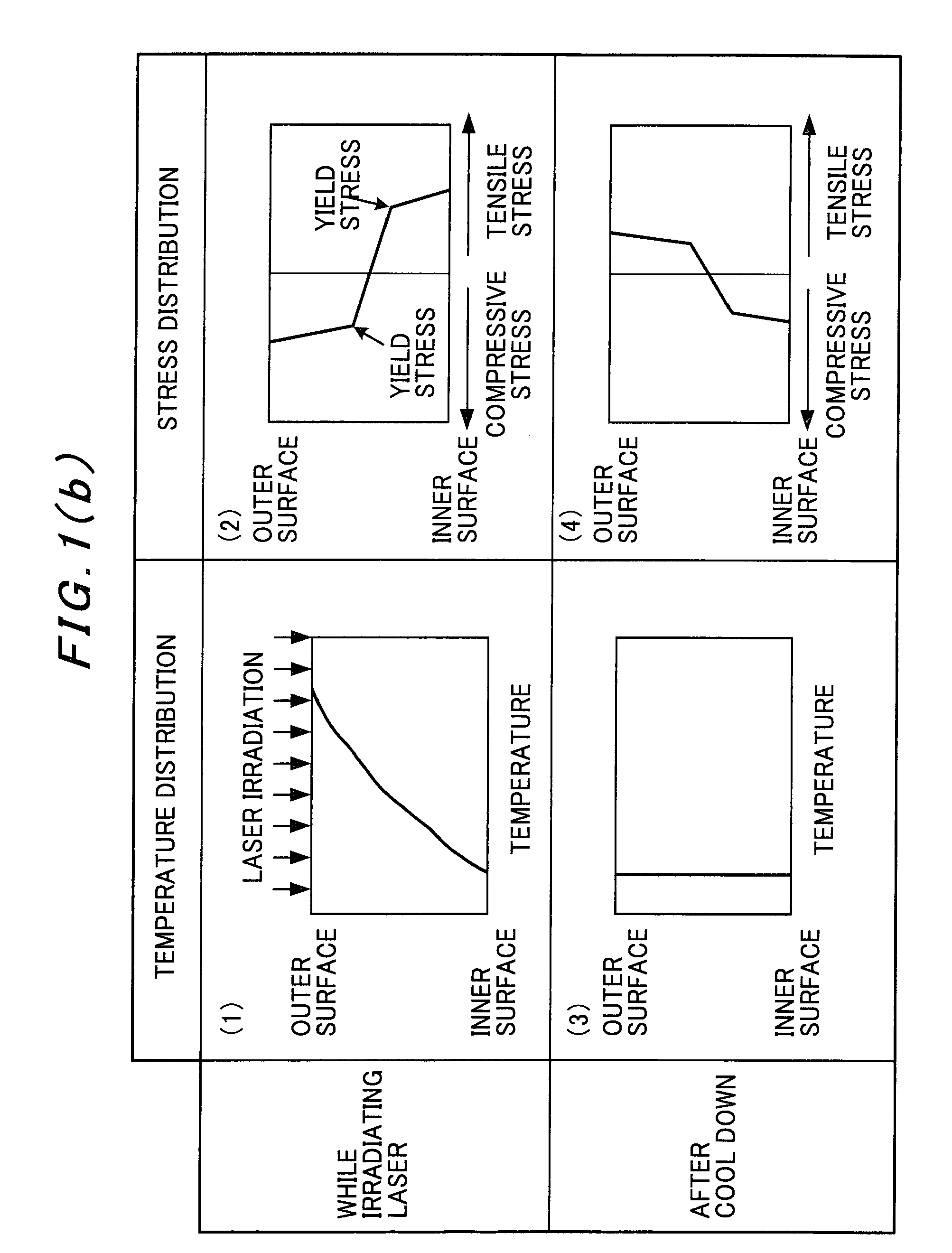
[0051]FIG. 1 is a view explaining a tube-body residual stress improving system according to the present invention and the principle thereof.

[0052]As shown in FIG. 1(a), a residual stress improving system 1 includes a support section 4, an optical head 5, a laser oscillator 7, and a controller 8. The support section 4 is extended in an axial direction L of a pipe 2 as a cylindrical tube body and can be rotated around the outer circumference of the pipe 2 coaxially with the pipe 2 by a not-shown rotary moving device. The optical head 5 is supported by the support section 4 and irradiates a laser beam onto a predetermined area of the outer circumferential surface of a welded part of the pipe 2. The laser oscillator 7 is connected to the optical head 5 by an optical fiber 6 and supplies the laser beam to the optical head 5 through the optical fiber 6. The controller 8 controls the rotational moving device, the laser oscillator 7, and the like. In an area where the outer circumferential ...

embodiment 2

[0065]FIG. 3 is a view explaining another example of the embodiment of the tube body stress improving method according to the present invention.

[0066]This embodiment is described based on the residual stress improving system 1 shown in Embodiment 1. Description of the constitution of the residual stress improving system 1 itself is therefore omitted. Embodiments 3 to 5 shown below are described based on the residual stress improving system 1 shown in Embodiment 1, as well, and therefore description of the constitution of the residual stress improving system 1 itself is omitted.

[0067]As shown in FIG. 3, in this embodiment, when the start and end angles θs and θe of laser irradiation to a tube body are 0° and 360° as circumferential positions, respectively, in other words, when the start angle θs=the end angle θe, the intensity of the laser beam is gradually increased from an intensity ratio of 0 to an intensity ratio of 1.0 as the steady intensity during rotation from the start angle...

embodiment 3

[0070]FIG. 4 is a view explaining still another example of the embodiment of the tube body stress improving method according to the present invention.

[0071]As shown in FIG. 4, in this embodiment, when the start and end angles θs and θe of laser irradiation to a tube body are 0° and 360° as circumferential positions, respectively, in other words, when the start angle θs=the end angle θe, the intensity of the laser beam is set to an intensity ratio of 1.0 as the steady intensity and keeps an intensity ratio of 1.0 during rotation from the start angle θs to the second predetermined angle θ2, which is short of the end angle θe (an steady output step). Next, during rotation from the second predetermined angle θ2 to the end angle θe, the intensity of the laser beam is gradually decreased from an intensity ratio of 1.0 to 0 (an output decreasing step) and caused to reach 0 at the end angle θe=360° (an output stop step). A cycle of all the above steps is performed at one turn of rotation fo...


PUM

PropertyMeasurementUnit
Temperatureaaaaaaaaaa
Ratioaaaaaaaaaa
Residual stressaaaaaaaaaa

Abstract

An object is to provide a method and a system for improving a residual stress in a tube body, with which the residual stress can reliably be improved without heating excessively. From an irradiation start angle θs to a first predetermined angle θ1 on the tube body, an intensity of a laser beam is gradually increased from 0.5 to the steady output of 1.0 output ratio; from the first predetermined angle θ1 to a second predetermined angle θ2, the intensity of the laser beam is set at 1.0 output ratio; from the second predetermined angle θ2 to an irradiation end angle θe, the intensity of the laser beam is gradually decreased from the 1.0 output ratio to 0.5; and at the irradiation end angle θe, the intensity of the laser beam is set to 0. All these steps are performed at one turn of rotation in the method and the system for improving residual stress in the tube body.

Description

TECHNICAL FIELD [0001]The present invention relates to a tube body residual stress improving method and a system to improve residual stress in a tube body such as a pipe.BACKGROUND ART [0002]In the case of laying tube bodies such as large pipes in nuclear power plants, large plants, and the like, removal of stress remaining in pipes at welding becomes an issue. Welding causes residual stress in a pipe, and the residual stress may shorten the life of the pipe. Accordingly, it is desirable to remove such residual stress caused by welding.[0003]As a method of removing residual stress in a pipe, the induction heating stress improvement process (hereinafter, referred to as the IHSI process) has been proposed. According to the IHSI process, outer surface part of a pipe is increased in temperature by induction heating using a high frequency induction heating coil while the inner surface thereof is forcedly cooled by running water so that the pipe has a temperature gradient in a thickness d...

Claims


Application Information

Patent Timeline
IPC IPC(8): B23K26/20B23K26/00B23K26/04B23K26/21B23K31/00C21D1/34C21D9/08
CPCB23K26/0626B23K26/0823B23K2201/06C21D9/50C21D1/34C21D9/08C21D1/30B23K2101/06
Inventor OTA, TAKAHIROHEMMI, YOSHIYUKIONITSUKA, HIRONORISUGIMOTO, NORIAKIKAMO, KAZUHIKOTSUBOTA, SHUHOMUROYA, ITARU
Owner MITSUBISHI HEAVY IND LTD
Why Eureka
Try Eureka