
Airless spray gun having a removable valve cartridge and protective insert

a valve cartridge and airless technology, applied in the direction of spray nozzles, spraying apparatus, spraying nozzles, etc., can solve the problems of coating fluid eventually wearing components, time-consuming and expensive maintenance process, and increase the time and cost of manufacturing, assembly, maintenance and cleaning of spray coating devices

Inactive Publication Date: 2009-12-10
CARLISLE FLUID TECH INC
View PDF41 Cites 40 Cited by
  • Summary
  • Abstract
  • Description
  • Claims
  • Application Information

AI Technical Summary

Benefits of technology

The spray coating system has a spray gun with a valve cartridge and a protective insert. The protective insert is placed in the passage of the spray gun and has a central passage to protect it from wear and tear caused by liquid flow through the body. The technical effect of this design is to improve the durability of the spray coating system and to prolong its lifespan.

Problems solved by technology

Unfortunately, the discrete nature of these components increases the time and costs associated with manufacture, assembly, maintenance, and cleaning of the spray coating device.
If a specific component becomes worn, then the maintenance process can be time consuming and expensive due the numerous discrete components assembled along with the worn component.
For example, the coating fluid may eventually wear the components (e.g., valves, seals, etc.) in the fluid path through the spray coating device.
Unfortunately, maintenance may involve sequentially removing and replacing a large number of discrete parts, thereby resulting in undesirable downtime.
The downtime is particularly undesirably in automated systems, such as assembly lines.
Without the maintenance, the spray coating device may produce undesirable spray patterns, non-uniform color distribution, leakage, clogging, and so forth.

Method used


Image

  • Airless spray gun having a removable valve cartridge and protective insert
  • Airless spray gun having a removable valve cartridge and protective insert
  • Airless spray gun having a removable valve cartridge and protective insert

Examples


Embodiment Construction

[0026]One or more specific embodiments of the present invention will be described below. In an effort to provide a concise description of these embodiments, all features of an actual implementation may not be described in the specification. It should be appreciated that in the development of any such actual implementation, as in any engineering or design project, numerous implementation-specific decisions must be made to achieve the developers' specific goals, such as compliance with system-related and business-related constraints, which may vary from one implementation to another. Moreover, it should be appreciated that such a development effort might be complex and time consuming, but would nevertheless be a routine undertaking of design, fabrication, and manufacture for those of ordinary skill having the benefit of this disclosure.

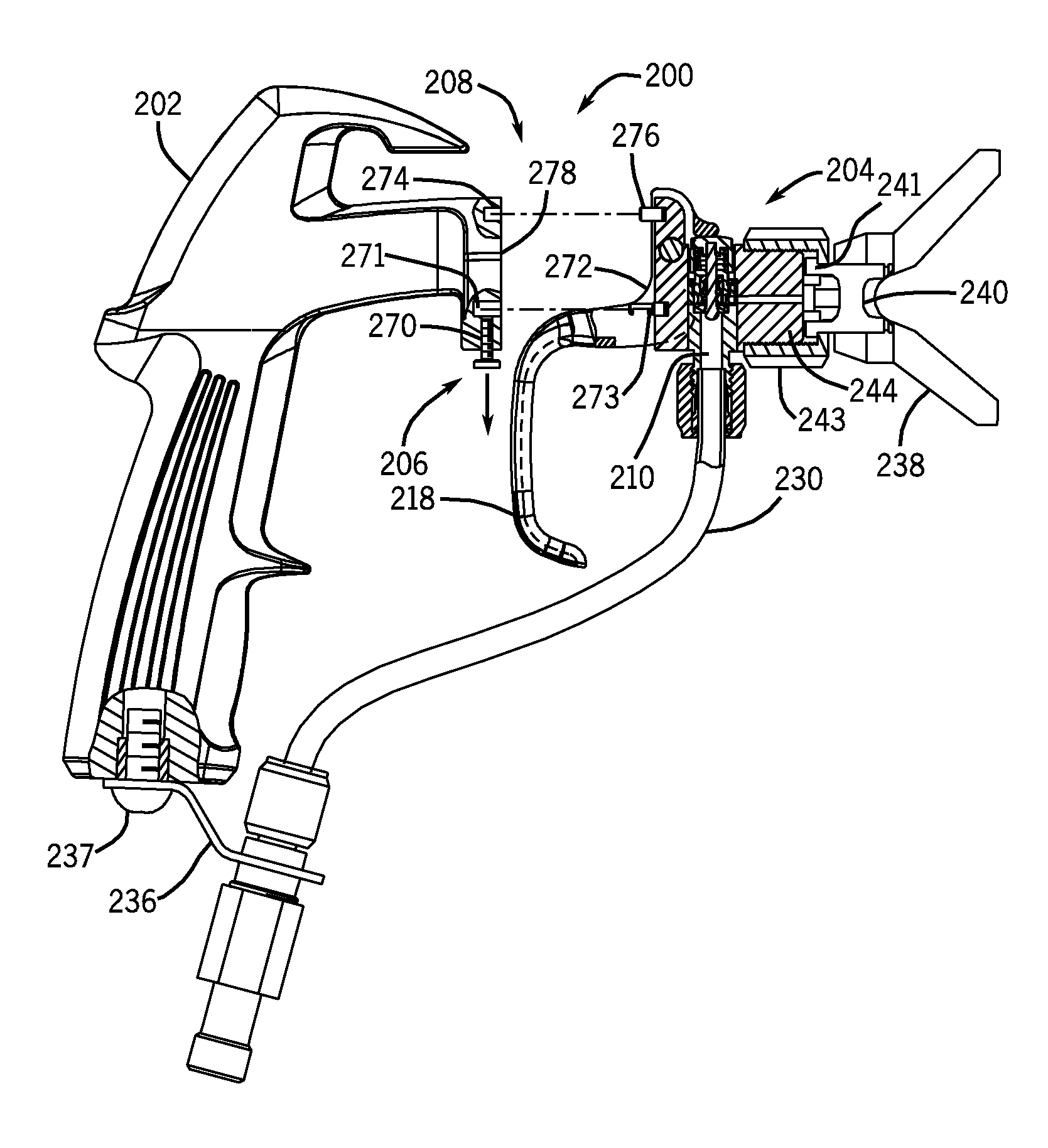
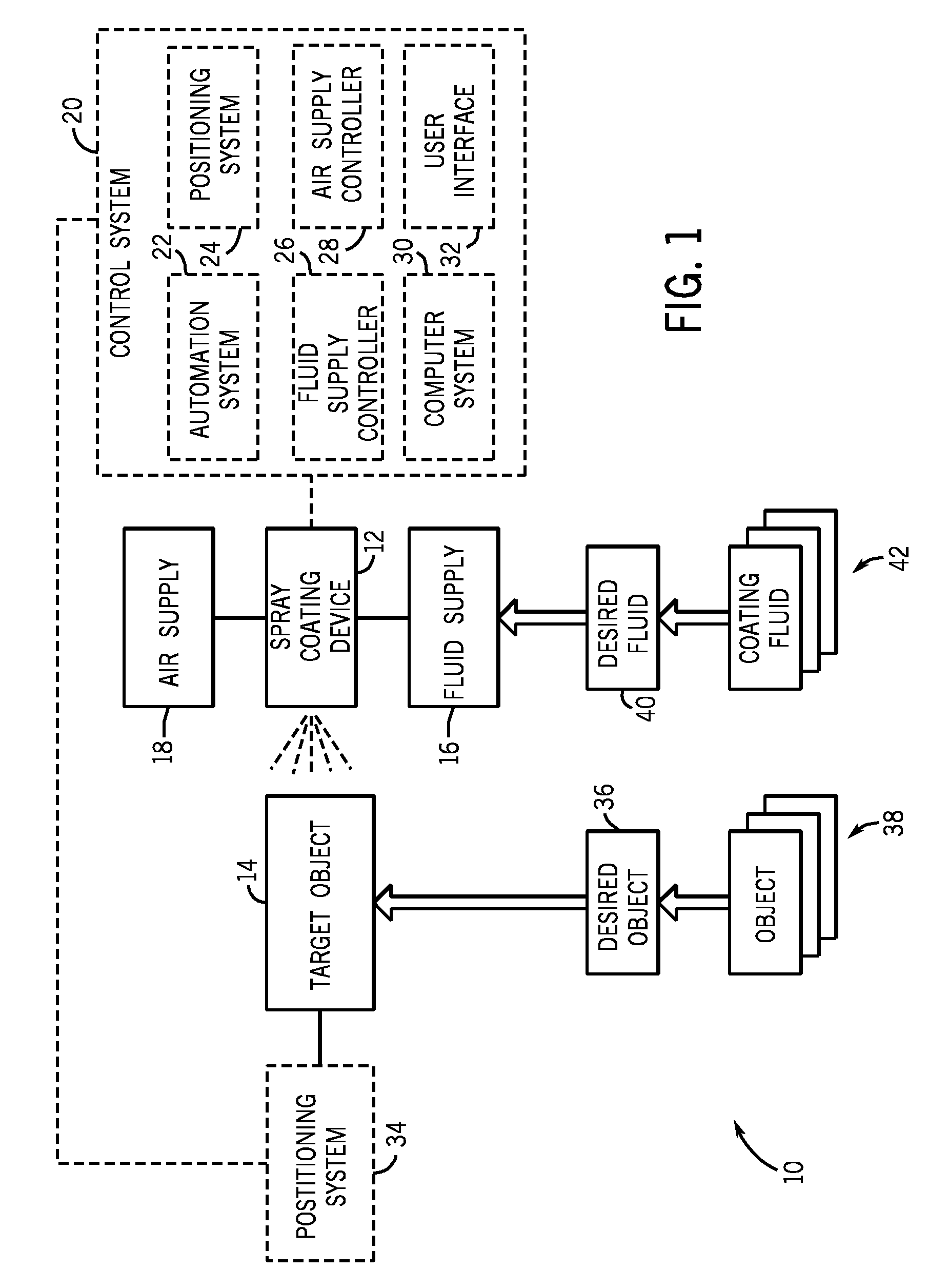
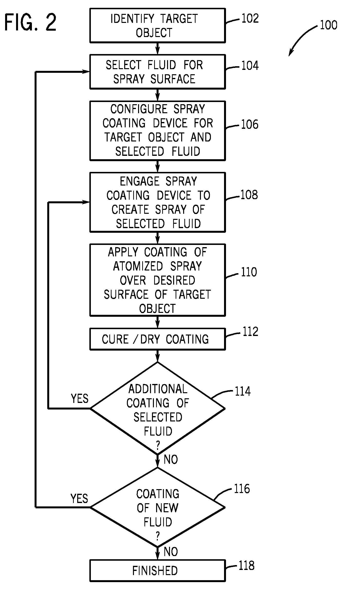
[0027]FIG. 1 is a flow chart illustrating an exemplary spray coating system 10, which comprises a spray coating device 12 for applying a desired coatin...


PUM


Abstract

A spray coating system, in one embodiment, includes a spray gun having a body, a valve cartridge, and a protective insert. The body includes a passage intersecting a receptacle. The valve cartridge is disposed in the receptacle. The protective insert is disposed in the passage. The protective insert has a central passage, and the protective insert protects the passage from wear by liquid flow through the body.

Description

CROSS-REFERENCE TO RELATED APPLICATION[0001]This application is a continuation-in-part of U.S. patent application Ser. No. 12 / 119,133, entitled “AIRLESS SPRAY GUN HAVING A REMOVABLE VALVE CARTRIDGE”, filed on May 12, 2008, which is herein incorporated by reference in its entirety.BACKGROUND[0002]The invention relates generally to spray coating systems and, more particularly, to an airless spray coating device with a removable valve cartridge.[0003]A typical spray coating device, such as a spray gun, includes a variety of discrete components, such as fluid valves, springs, conduits, and so forth. These discrete components are individually and / or sequentially assembled into a body of the spray coating device. Unfortunately, the discrete nature of these components increases the time and costs associated with manufacture, assembly, maintenance, and cleaning of the spray coating device. If a specific component becomes worn, then the maintenance process can be time consuming and expensive...

Claims


Application Information

Patent Timeline
Patent Type & Authority Applications(United States)
IPC IPC(8): B05B1/32
CPCB05B1/302B05B3/02B05B5/0403B05B15/061B05B9/01B05B13/04B05B7/02B05B15/62
Inventor MICHELI, PAUL R.GAJJAR, NEKHEEL
Owner CARLISLE FLUID TECH INC
Learn More