Multi-Element Resonant Converters

a resonant converter and multi-element technology, applied in the direction of electric variable regulation, process and machine control, instruments, etc., can solve the problems of large current circulation, limited efficiency which can be achieved by hard-switching converters, and significant conduction losses

Inactive Publication Date: 2009-12-10
VIRGINIA TECH INTPROP INC
View PDF3 Cites 120 Cited by
  • Summary
  • Abstract
  • Description
  • Claims
  • Application Information

AI Technical Summary

Benefits of technology

[0012]In order to accomplish these and other objects of the invention, a multi-element DC / DC power converter is provided comprising a switched power input circuit and a resonant tank circuit comprising at least four elements, said resonant tank circuit providing a band pass filter resonant at a first frequency, a notch filter resonant at a second frequency higher than said first frequency. A further band pass filter resonant at a frequency which is a harmonic of the first frequency can increase power transfer to a load at harmonics of the switching frequency. All required inductive and transformer elements can also be integrated into a single electrical component.

Problems solved by technology

However, the efficiency which can be achieved by hard-switching converters is limited by the switching losses which become especially severe as switching frequencies are increased.
However, the resonant circuit causes large currents to circulate within the converter, particularly at harmonics of the switching frequency, and conduction losses can be significant.
Therefore, bulky capacitors are used to provide energy during the holdup time.
Thus the capacity of the holdup time capacitor is wholly determined by required energy during holdup time and severely limits the capability for increasing increased power density even though increasing the operating range can extract more power from the holdup capacitor and allow a capacitor of somewhat reduce value to be employed.
Unfortunately, sacrifice of a significant degree of efficiency is required to extend the operating range in order to do so through known techniques.
While some arrangements have been proposed for extending operational range and extending holdup time for a given capacitance, they are complex and difficult to control.
While LLC converters can achieve zero voltage switching (ZVS) and zero current switching (ZCS) together with high voltage gain capability suitable for reducing the holdup capacitance requirement, currents during start up and short circuit conditions excessively stresses internal components, compromising reliability.
Further, the magnitude of circulating resonant currents is aggravated; imposing an increased limitation of efficiency.

Method used


Image

  • Multi-Element Resonant Converters
  • Multi-Element Resonant Converters
  • Multi-Element Resonant Converters

Examples


Embodiment Construction

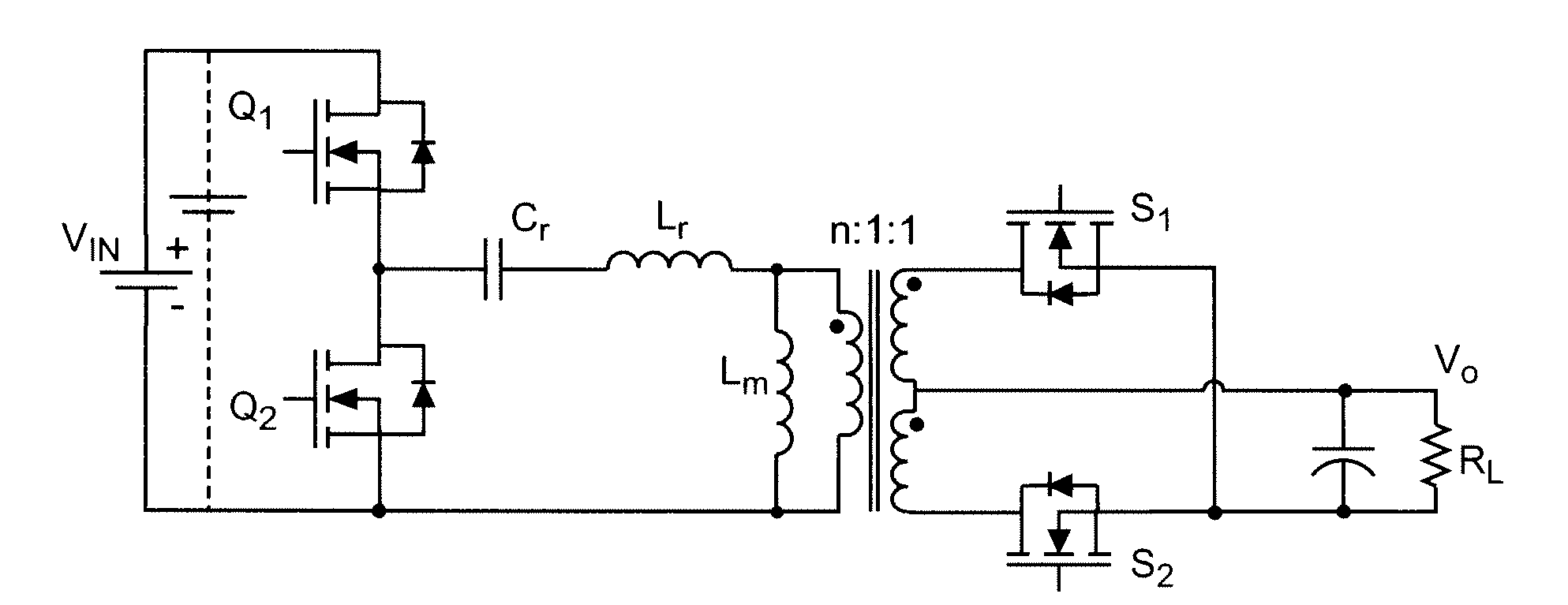
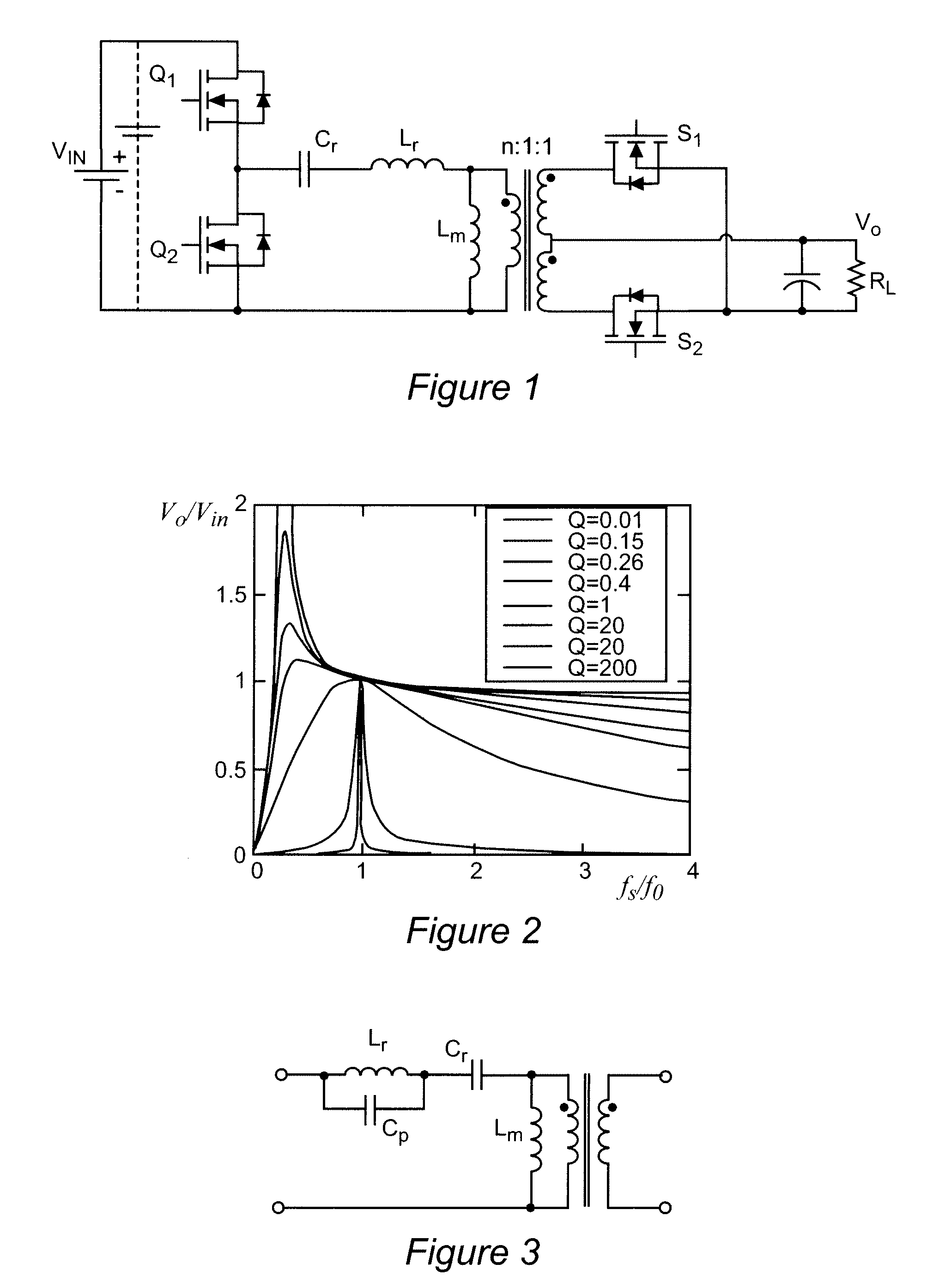
[0035]Referring now to the drawings, and more particularly to FIG. 1, a schematic diagram of an exemplary LLC resonant converter circuit, alluded to above, is shown. The general principles of operation of such an LLC resonant converter will be familiar to those skilled in the art. However, since this circuit is exemplary and arranged to facilitate discussion of the problems addressed by the present invention, no portion of FIG. 1 is admitted to be prior art as to the present invention. Essentially, switches Q1 and Q2 conduct alternately and provide a square wave input to capacitor Cr forming a part of an LLC resonant tank circuit comprising Cr, Lr and Lm such that the square pulse input when Q1 is conductive is converted to a half-sinusoid pulse that returns to approximately zero when, at a particular switching frequency, Q1 is to be turned off and Q2 turned on to achieve zero voltage switching (ZVS) and zero current switching (ZCS) as alluded to above. The sinusoidal waveform thus ...


PUM


Abstract

A resonant switched power converter having switching frequency controlled in response to an output voltage thereof achieves over-current protection such as at start-up or under short circuit conditions using a resonant tank circuit which provides a notch filter in addition to a band pass filter. A additional band pass filter provided in the resonant tank circuit achieves increased power transfer to a load and reduced circulating resonant currents and conduction losses. The inductances of the preferred LCLCL tank circuit or other tank circuit with two pass band filters and a notch filter may be integrated into a single electrical component.

Description

BACKGROUND OF THE INVENTION[0001]1. Field of the Invention[0002]The present invention generally relates to power supply systems and voltage converters and, more particularly, to resonant DC / DC converters and power supplies having four or more resonating elements to achieve both increased efficiency and other desired characteristics such as start-up and short-circuit over-current protection.[0003]2. Description of the Prior Art[0004]Many currently available and foreseeable commercial electronic products provide for operation from DC power sources such as rechargeable batteries but also provide for obtaining power from commonly available AC distribution systems. Many such devices include digital logic circuitry which may be of a wide range of complexity and which may include technologically advanced components with stringent tolerances for voltage and current requirements including widely varying current demands at very low voltages such as are encountered in providing power to microp...

Claims


Application Information

Patent Timeline
Patent Type & Authority Applications(United States)
IPC IPC(8): H02M3/335
CPCH02M3/33592H02M3/3376Y02B70/1491Y02B70/1475H02M2001/0058Y02B70/1433H02M1/126Y02B70/10Y02P80/10H02M3/33571H02M3/01H02M1/0058
Inventor FU, DIANBOLEE, FRED C.LIU, YAXU, MING
Owner VIRGINIA TECH INTPROP INC
Why Eureka
Try Eureka