
Method, Server Device and Converting Device for Setting Up a Payload-Data Connection

a payload data and server device technology, applied in the field of communication systems, can solve problems such as quality loss by the decoder, and achieve the effect of avoiding quality loss due to multiple conversions of payload data and avoiding loss of payload data quality

Active Publication Date: 2009-12-10
UNIFY GMBH & CO KG
View PDF9 Cites 12 Cited by
  • Summary
  • Abstract
  • Description
  • Claims
  • Application Information

AI Technical Summary

Benefits of technology

[0020]The method according to the invention is advantageous to the extent that, where the verification ascertains compatibility, a payload data connection can be set up from the source communications device to the target communications device via a single converting device and consequently only minor losses of quality occur in the quality of the payload data. The method can advantageously be used where a direct payload-data connection is not possible, in particular due to incompatible encoders and decoders between the source communications device and the target communications device, or where this is possible only with an encoder and decoder not suited to an available bandwidth.
[0024]The payload data can preferably be transmitted directly from the source communications device to the converting device without further converting devices being located in the transmission path of the payload data. The same applies to transmission from the converting device to the target communications device. In this way, losses of quality due to multiple conversions of the payload data can be avoided.
[0025]In an advantageous further development of the inventive method, one or more of the non-selected converting devices that are located in the signaling path between the source communications device and the target communications device can be bypassed in the transmission of the payload data. Losses of quality of the payload data through multiple encoding and decoding or due to delays caused by multiple buffering of the payload data in jitter buffers can thus be avoided. This applies in particular where the payload data is transmitted exclusively via the selected converting device, bypassing the non-selected converting devices, and consequently only a single converting device is involved in the transmission of the payload data.

Problems solved by technology

An encoder and a decoder are deemed compatible with one another if a data stream encoded by the encoder can be decoded—possibly with losses of quality—by the decoder.

Method used


Image

  • Method, Server Device and Converting Device for Setting Up a Payload-Data Connection
  • Method, Server Device and Converting Device for Setting Up a Payload-Data Connection
  • Method, Server Device and Converting Device for Setting Up a Payload-Data Connection

Examples


Embodiment Construction

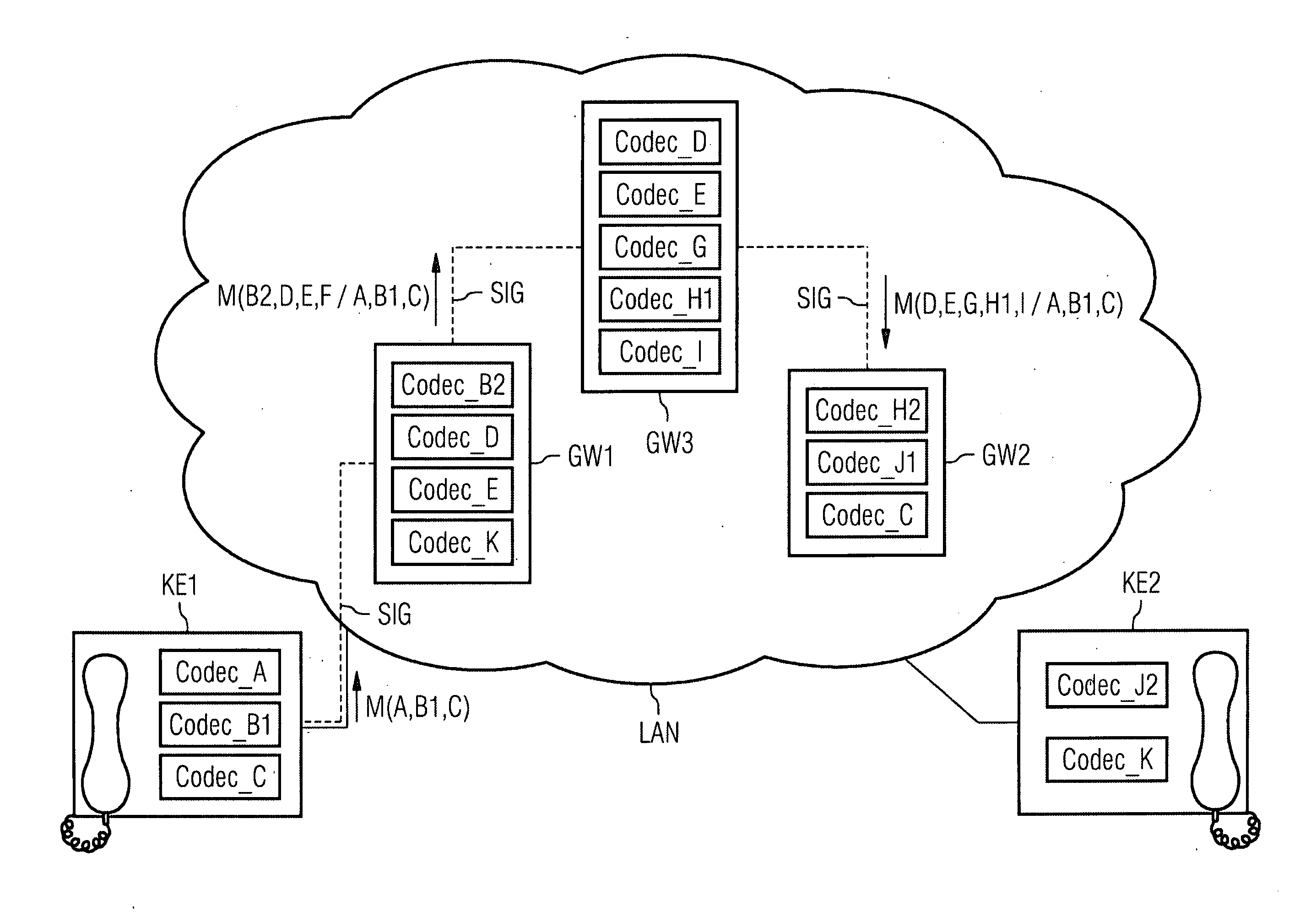
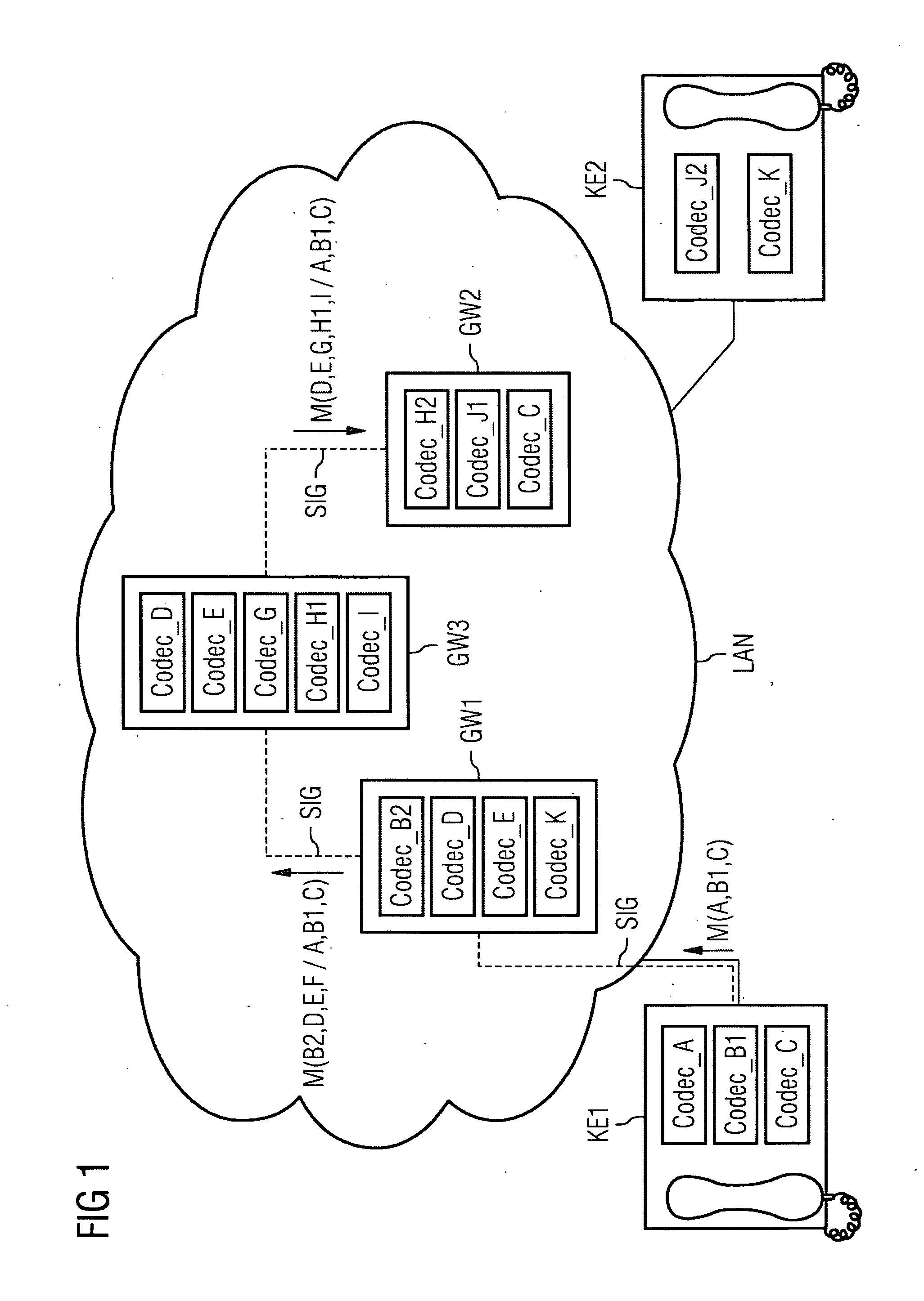
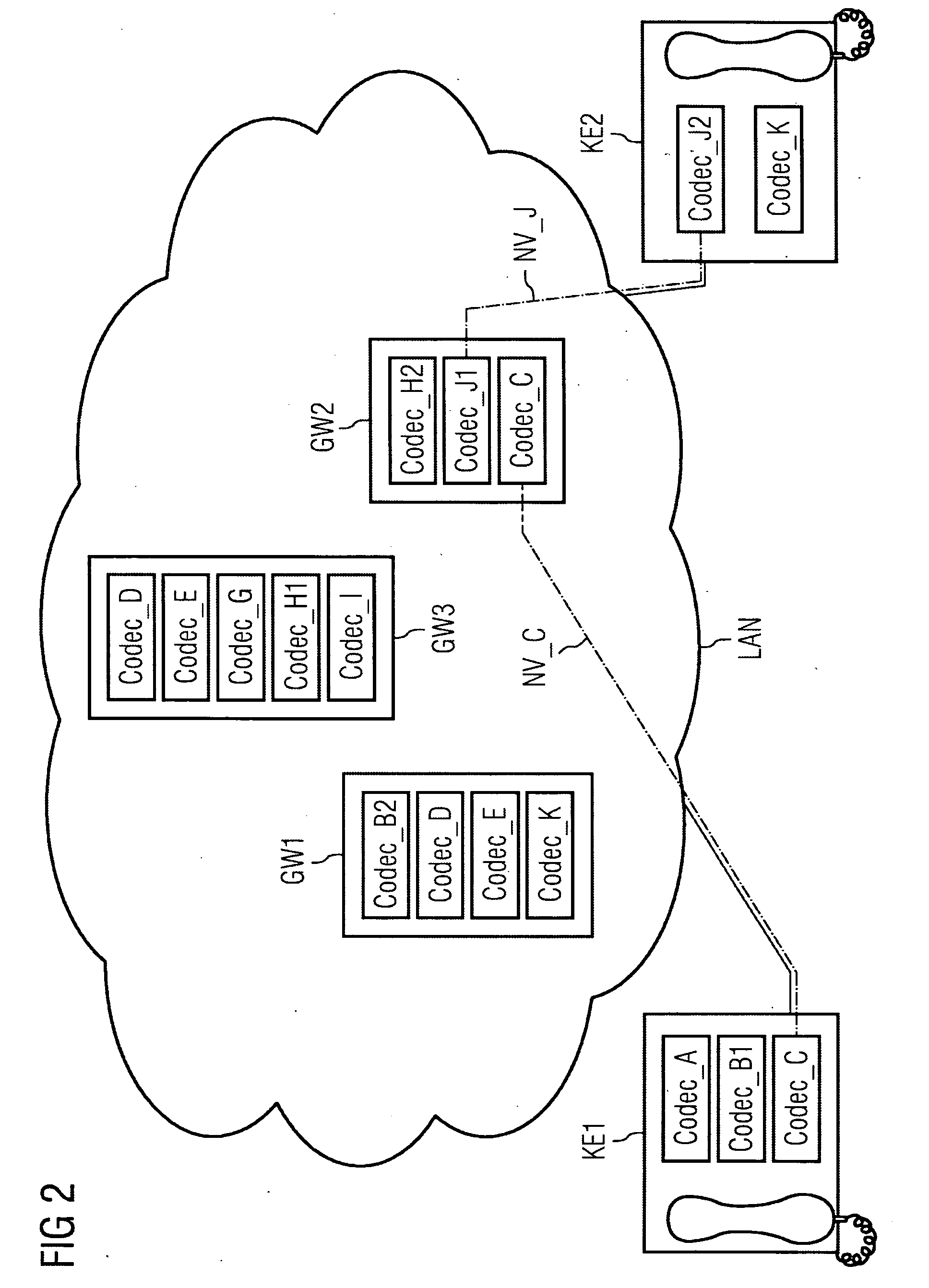
[0041]FIGS. 1-4 and FIG. 7 represent diagrammatically a communications system comprising a first IP telephone KE1 as a source communications device and a second IP telephone KE2 as a target communications device. The first encoder of the first IP telephone KE1 is one of the codecs CODEC_A, CODEC_B1 and CODEC_C. The first decoder of the second IP telephone KE2 is one of the codecs CODEC_J2 and CODEC_K. Here, a designation “CODEC_B1” is intended to signify that this codec is compatible with a CODEC_B2, CODEC_B3, etc., but not with a CODEC_A or CODEC_C. CODEC_B1, CODEC_B2, CODEC_B3, etc. are thus mutually compatible codecs based on a codec CODEC_B. If in the exemplary embodiment two devices support the same codec, e.g. CODEC_D, then this means that both use the same codec for encoding and decoding. This means that the encoder of a codec and the decoder of a codec are matched to one another and are thus in particular also compatible. It is assumed that the codecs in the exemplary embodi...


PUM


Abstract

There is described a transmission of user data from a source communications device provided with a first encoder for encoding users data to a target communications device provided with a first decoder for decoding said user data via a communication network which is provided with several converting devices comprising additional encoders and additional decoders for carrying out a verification of the converting devices. Via the verification it is determined, whether the first encoder is compatible with the decoder of a given converting device and, whether the first decoder is compatible with the encoder of said converting device. One of the converting devices for which the compatibility is ascertained by the verification is selected for transmitting user data. During transmission of the user data, said user data encoded with the aid of the first encoder is decoded with the aid of the compatible decoder of the converting device and the user data decodable with the aid of the first decoder is encoded with the aid of the compatible encoder of the selected converting device.

Description

CROSS REFERENCE TO RELATED APPLICATIONS[0001]This application is the US National Stage of International Application No. PCT / EP2006 / 063051, filed Jun. 9, 2006 and claims the benefit thereof. The International Application claims the benefits of German application No. 10 2005 031 167.9 DE filed Jul. 4, 2005, both of the applications are incorporated by reference herein in their entirety.FIELD OF INVENTION[0002]The invention relates to a communication system using a network to transmit payload data.BACKGROUND OF INVENTION[0003]In contemporary communications systems, it is known for payload data, e.g. relating to voice, video or multimedia communication, to be transmitted via packet-oriented networks. The use of packet-oriented data transmission methods frequently results in losses in the quality of the payload data being transmitted, such losses frequently being due to conversions and delays of payload-data packets in network nodes.[0004]Based upon the frequently used Internet Protocol,...

Claims


Application Information

Patent Timeline
IPC IPC(8): H04L12/66
CPCH04L29/06027H04M7/0072H04L65/103H04L65/104H04L65/1043H04L65/1101
Inventor KENNEDY, STEPHAN
Owner UNIFY GMBH & CO KG
Learn More