
Systems and Methods for Speculative Signal Equalization

a signal equalization and signal technology, applied in the field of system and channel equalization, can solve the problems of channel distortion and attenuation, inter symbol interference (isi), noise, jitter and the like, and may not be sufficient for receivers,

Inactive Publication Date: 2009-12-10
AVAGO TECH WIRELESS IP SINGAPORE PTE
View PDF24 Cites 26 Cited by
  • Summary
  • Abstract
  • Description
  • Claims
  • Application Information

AI Technical Summary

Benefits of technology

[0001]The present inventions are related to systems and methods for processing dig

Problems solved by technology

At such high frequencies, channel distortion and attenuation, such as Inter Symbol Interference (ISI), crosstalk, noise, jitter, and the like becomes significant.
In some cases, however, such an approach may increase various noise components resulting in an undesirable decrease in signal to noise ratio.
Further, such emphasis / de-emphasis approaches may not be sufficient in many systems and channels to permit the receiver to recover the bit sequence.
While such maximum likelihood detectors can be very effective in determining a correct bit sequence, they typically require a great deal of semiconductor area to implement and introduce considerable latency to a data receiving process.
Such analog DFEs are capable of high bandwidth operation, but are typically expensive in terms of both power dissipation and semiconductor area.
However, existing digital equivalents offer lower bandwidth due to a variety of mathematical operations being accomplished in the digital signal domain.
At least in part because of this, many high bandwidth serializer / deserializer transceivers utilize analog DFEs at the cost of higher power dissipation and semiconductor area.
In some cases, such a cost is unacceptable.

Method used


Image

  • Systems and Methods for Speculative Signal Equalization
  • Systems and Methods for Speculative Signal Equalization
  • Systems and Methods for Speculative Signal Equalization

Examples


Embodiment Construction

[0022]The present inventions are related to systems and methods for processing digital signals, and more particularly to systems and methods for equalizing signals.

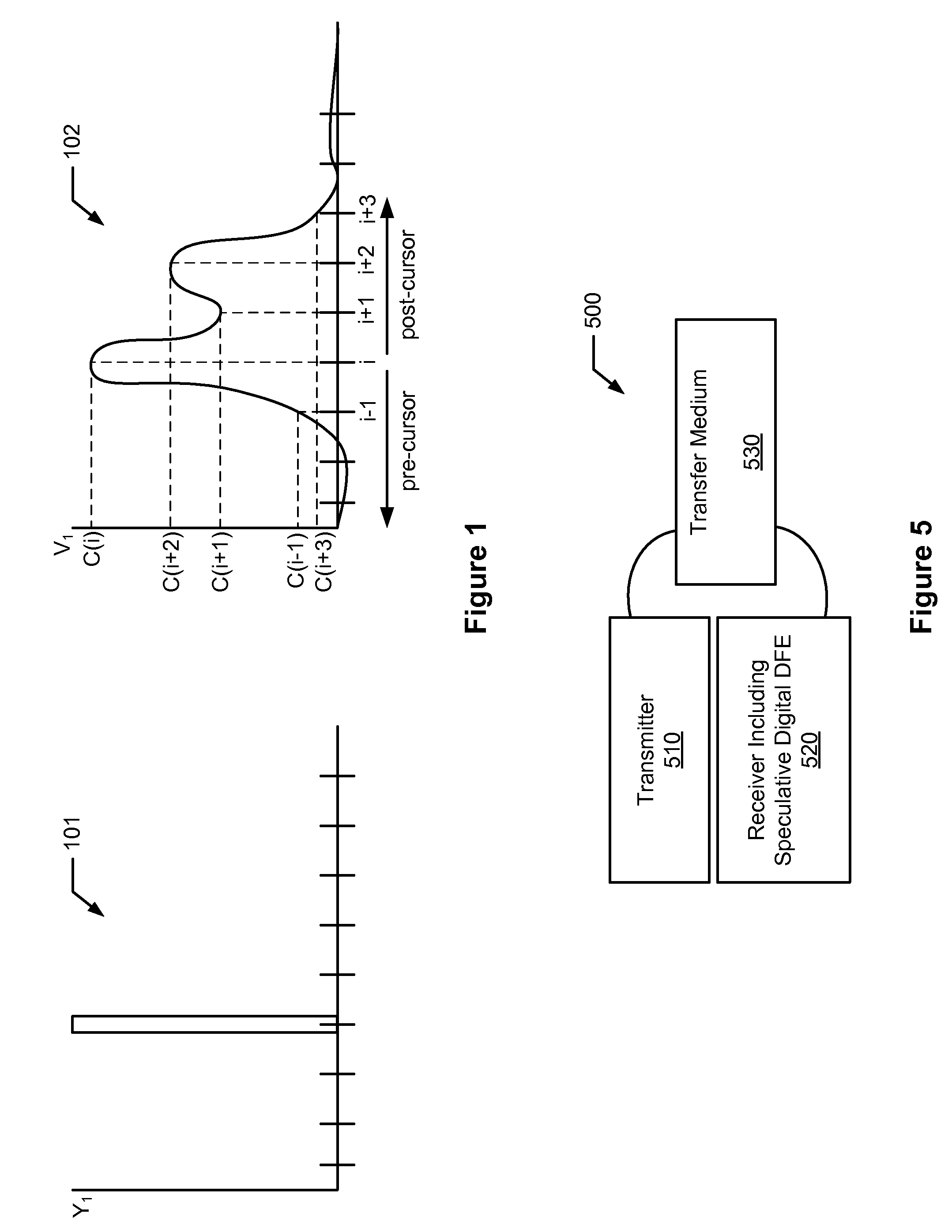
[0023]Turning to FIG. 1, an exemplary pulse 101 applied to a channel, and a channel response 102 thereto are depicted. C(i) indicates the magnitude of the impulse response (i.e., cursor); C(i−1) indicates the pre-cursor inter symbol interference at a bit period i−1; and C(i+1), C(i+2) and C(i+3) indicate post-cursor inter symbol interference at bit periods i+1, i+2 and i+3, respectively. From this, it is understood that an analog input signal representing a bit value during bit period i will interfere with the analog input signal during the previous bit period i−1, and during subsequent bit periods i+1, i+2 and i+3. Accordingly, the analog input signal during bit periods i−1, i+1, i+2 and i+3 bit periods will interfere with the analog input signal during bit period i. Thus, to compensate for inter symbol interference, int...


PUM


Abstract

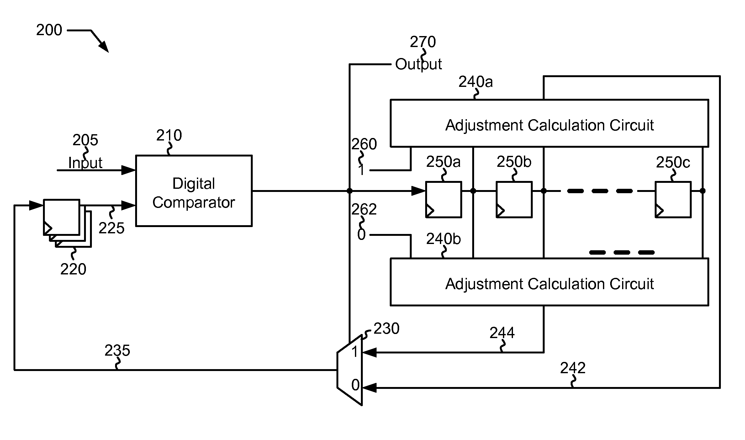
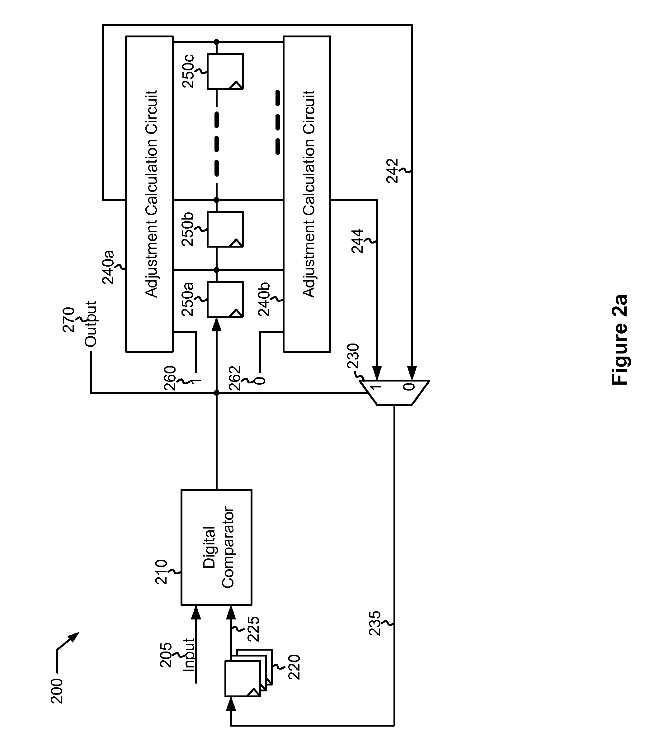
Various embodiments of the present invention provide systems and methods for signal equalization, and in some cases analog to digital conversion. For example, an analog to digital converter is disclosed that includes a comparator bank that receives a reference indicator and is operable to provide a decision output based at least in part on a comparison of an analog input with a reference threshold corresponding to the reference indicator. A range selection filter is included that has a first adjustment calculation circuit and a second adjustment calculation circuit. The first adjustment calculation circuit is operable to calculate a first adjustment feedback value based at least in part on a speculation that the decision output is a first logic level, and the second adjustment calculation circuit is operable to calculate a second adjustment feedback value based at least in part on a speculation that the decision output is a second logic level. A selector circuit selects the first adjustment feedback to generate the reference indicator when the decision output is the first logic level, and selects the second adjustment feedback to generate the reference indicator when the decision output is the second logic level.

Description

BACKGROUND OF THE INVENTION[0001]The present inventions are related to systems and methods for processing digital signals, and more particularly to systems and methods for equalizing signals.[0002]High speed serial communication has become popular and essential in current communication devices. Serializer / deserializer transceivers have been developed to serialize a number (P) of parallel signals each of a given bit rate (B) into a single serial signal with a rate of P*B. The single signal may then be transmitted to a receiver and subsequently deserialized into an output corresponding to the original P parallel signals with the original bit rate B. Common serializer / deserializer transceivers can transmit serial signals up to approximately 10 Gbps. At such high frequencies, channel distortion and attenuation, such as Inter Symbol Interference (ISI), crosstalk, noise, jitter, and the like becomes significant.[0003]In some cases, signal degradation due to one or more of the aforemention...

Claims


Application Information

Patent Timeline
IPC IPC(8): H03H7/30H03K5/159
CPCH03M1/002H03M1/004H04L25/03057H03M1/367H03M1/361
Inventor CHMELAR, ERIKITO, CHOSHULOH, WILLIAM
Owner AVAGO TECH WIRELESS IP SINGAPORE PTE
Learn More