Simulation-based functional verification of microcircuit designs

a micro-circuit and simulation-based technology, applied in the field of simulation-based functional verification of micro-circuit designs, can solve the problems of not providing a large enough coverage, preventing the use of exclusive use of such methods, and aggravated difficulty, so as to improve the confidence in the coverage of the dut, the effect of broad coverage and deep coverag

Inactive Publication Date: 2006-10-31
SYNOPSYS INC
View PDF6 Cites 63 Cited by
  • Summary
  • Abstract
  • Description
  • Claims
  • Application Information

AI Technical Summary

Benefits of technology

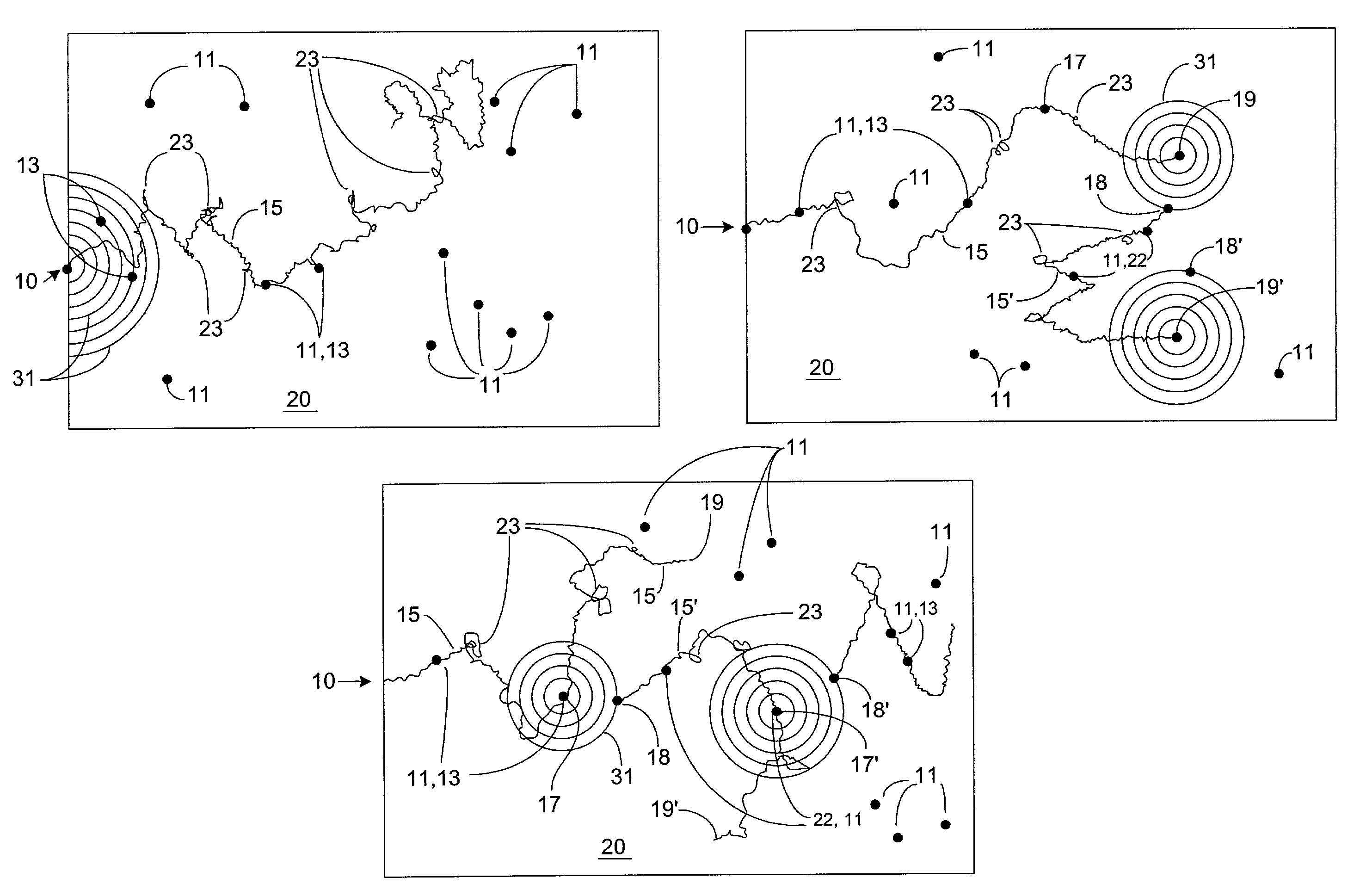
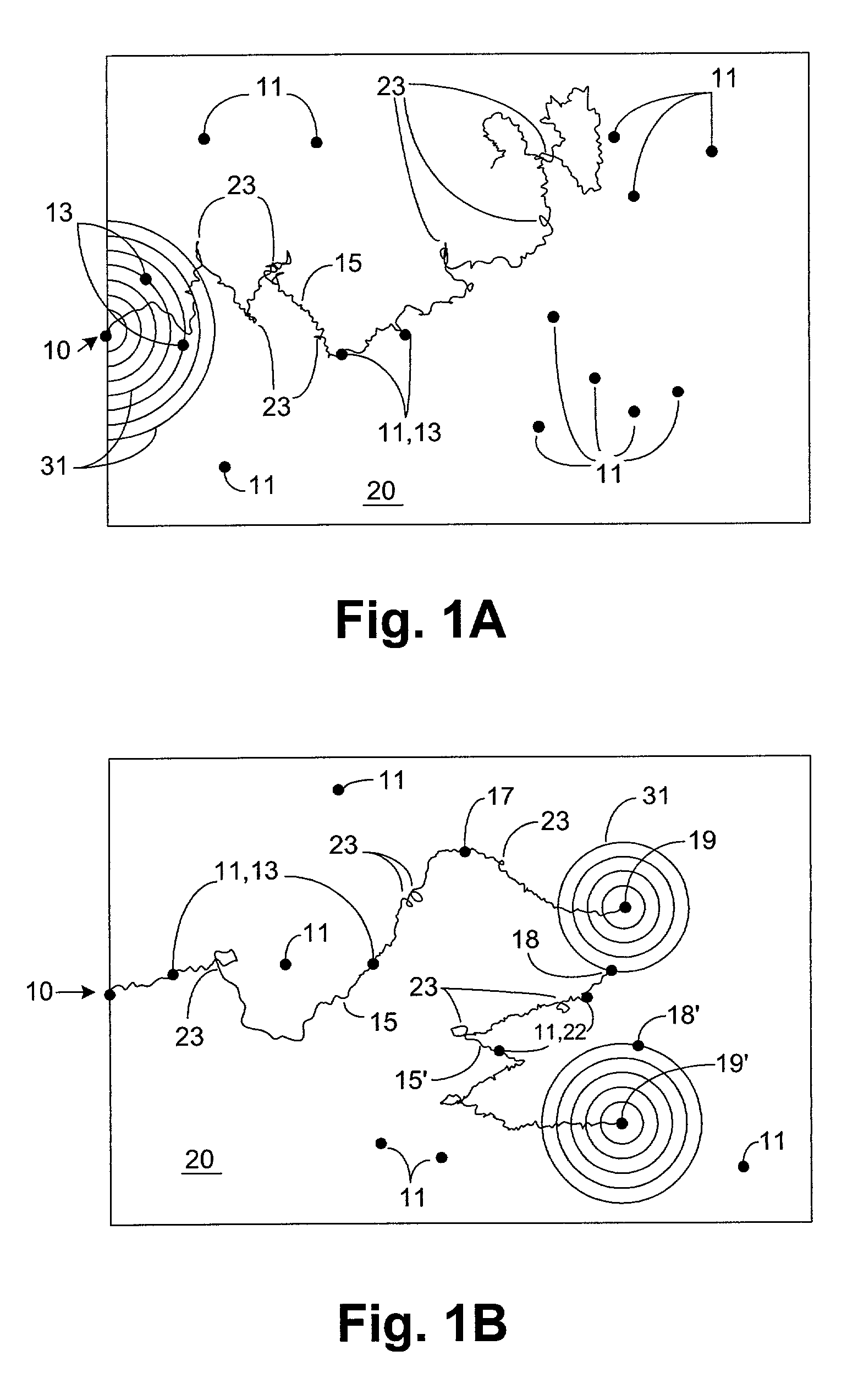
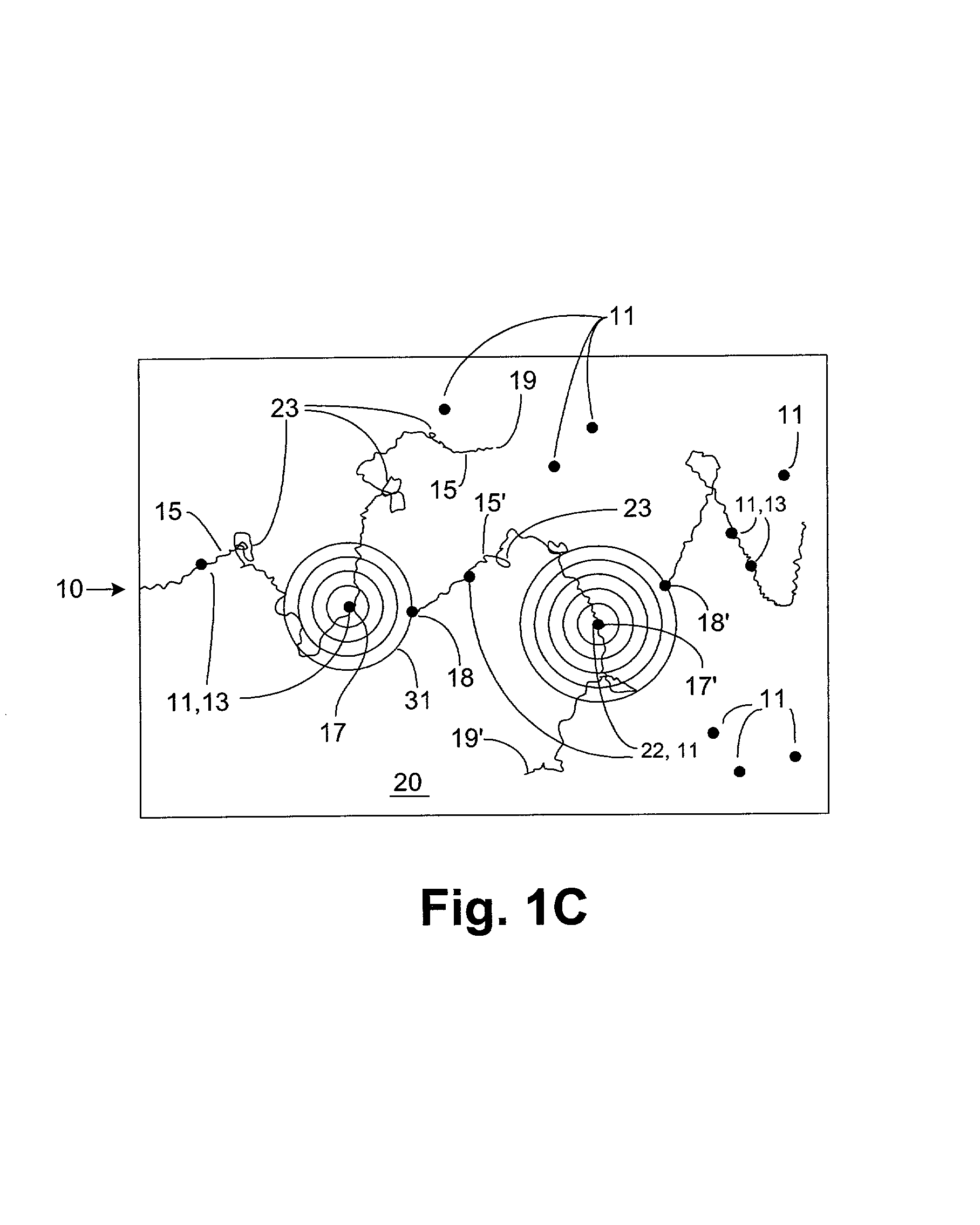
[0011]Preferably the DUT model used by the formal and random simulation methods are the same, or at least highly compatible, in order to save modeling and computation time.
[0014]The interleaving process is one of the most advantageous aspects of the invention. By switching back and forth between formal and random simulation methods, and particularly from states identified through random simulation, both broad and deep coverage of the DUT state space may be obtained and an improved confidence in coverage of the DUT gained.

Problems solved by technology

Such methods provide for relatively deep penetration of the space of possible states, but do not provide acceptably broad coverage.
This difficulty is aggravated by the observed tendency of even sophisticated random input generators to provide identical or very similar input sequences, or otherwise produce identical or similar DUT register states, on a repeated basis.
Such methods provide potentially complete coverage of the state space, but for even moderately complex DUTs the state space is so large that time and resource limits preclude the exclusive use of such methods from being effective.
Typically there exist a number of tasks a circuit is designed to do, and a number of things that are recognized as undesirable for the circuit to do—that is, there exist a number of circuit states which it is desirable or undesirable for the circuit to assume.

Method used


Image

  • Simulation-based functional verification of microcircuit designs
  • Simulation-based functional verification of microcircuit designs
  • Simulation-based functional verification of microcircuit designs

Examples


example

[0080]A data processing system is configured to perform a verification simulation process according to the above. The system comprises distinct program modules as shown in FIG. 3, including a user interface 152; a master control process 154; and random simulation, symbolic simulation, satisfiability, and unreachability slave processes 158, 160, 162, and 164 respectively. The system and its operation are described in the Design and Maintenance Specification for CTG Reachability & Control Subsystems attached hereto as Appendix 1.

[0081]The user interface is interactive and comprises the UNIX operating system, including standard UNIX commands such as “fork’ and ‘exec’. Commands are issued to the master control process via a UNIX pipe which feeds inputs to the master control process as standard input. The user interface may operate the system in either graphical or textual mode.

[0082]Master control process 154 is written in the C programming language, and uses a Task Control Language (“T...


PUM


Abstract

System, methods, and apparatus for verifying microcircuit designs by interleaving between random and formal simulation techniques to identify input traces useful for driving designs under test into sequences of device states. In a method aspect the invention provides process for beginning random simulation of a sequence of states of a microcircuit design by inputting a sequence of random input vectors to a design under test model in order to obtain a sequence of random simulation states; monitoring a simulation coverage progress metric to determine a preference for switching from random simulation to formal methods of simulating states in the design under test; beginning formal simulation of states in the design under test and monitoring a formal coverage progress metric to determine a preference for resuming random simulation of states of said microcircuit design; and resuming random simulation. Preferably the process of interleaving simulation methods continues until an input vector suitable for driving the design under test model into each of a set of previously-identified goal states has been obtained.

Description

COPYRIGHT NOTICE[0001]A portion of the disclosure of this patent document contains material which is subject to copyright protection. The copyright owner has no objection to the facsimile reproduction by anyone of the patent document or the patent disclosure, as it appears in the Patent and Trademark Office patent files or records, but otherwise reserves all copyrights whatsoever.BACKGROUND OF THE INVENTION[0002]The invention relates to systems and methods for verifying the design of digital microcircuits. Such digital microcircuits are now commonplace, and are used in a wide variety of applications, from desktop computers to television controls and common appliances to controllers for machinery, sophisticated weapons systems, and supercomputers. The digital microcircuit design to be tested shall be referred to as the design under test (DUT).[0003]More particularly, the present invention relates to systems and methods applied to a high-level DUT model with the purpose of generating ...

Claims


Application Information

Patent Timeline
Patent Type & Authority Patents(United States)
IPC IPC(8): G06F9/44G06F17/50G06F11/22
CPCG06F11/261G06F17/5022G06F17/504G06F30/33G06F30/3323
Inventor HARER, KEVIN M.HO, PEI-HSINDAMIANO, ROBERT F
Owner SYNOPSYS INC
Why Eureka
Try Eureka