Method for Producing Nanoparticles

a nanoparticle and nanotechnology, applied in the field of nanoparticle production, can solve the problems of complex operations to remove nanoparticles, inconvenient wet and dry processes in the related art, and the description of wet and dry processes, etc., and achieve the effect of not easy to aggrega

Active Publication Date: 2009-12-10
NAGOYA UNIVERSITY
View PDF2 Cites 12 Cited by
  • Summary
  • Abstract
  • Description
  • Claims
  • Application Information

AI Technical Summary

Benefits of technology

[0010]According to the method for producing nanoparticles, it is possible to produce nanoparticles that do not aggregate easily in a liquid without its surface modification by attaching the atoms or molecules constituting the nanoparticle precursor to the ionic liquid. Furthermore, it is possible to produce nanoparticles without the need for a complicated operation or the formation of a by-product because of the direct production of the nanoparticles from the nanoparticle precursor.

Problems solved by technology

Unfortunately, the wet and dry processes in the related art have problems described below.
The resulting nanoparticles, therefore, are not suitable for applications such as highly active catalysts having active sites on their particle surface.
Furthermore, the reaction solution contains salts as by-products and / or decomposition products; hence, complicated operations to remove them are required.
However, the resulting nanoparticles have a broad particle size distribution, and it is thus difficult to provide nanoparticles having a uniform particle size.
Furthermore, the dry processes provide the small amounts of products formed compared with the amounts of raw materials used, thus leading to high production costs.
Moreover, the resulting nanoparticles are fixed on the substrate; hence, it is difficult to collect the nanoparticles as a powder.
However, the nanoparticles are covered with the surfactant; hence, the process is not suitable for applications that use particle surfaces as active sites, as in the wet process.

Method used


Image

  • Method for Producing Nanoparticles
  • Method for Producing Nanoparticles
  • Method for Producing Nanoparticles

Examples


example 1

[0033](1) Production of Gold Nanoparticles with EMI-BF4

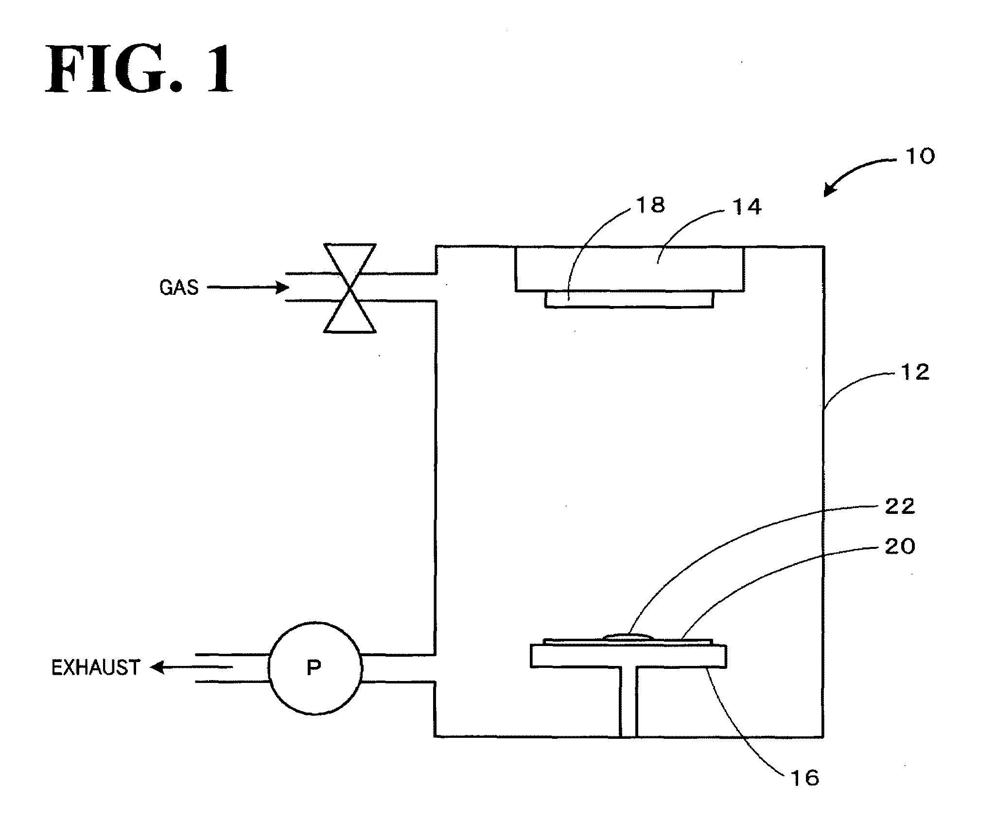
[0034]On a slide glass (26 mm×76 mm), 0.60 cm3 of 1-ethyl-3-methylimidazolium tetrafluoroborate (EMI-BF4) was evenly placed. At this time, the EMI-BF4 was not spilled from the glass substrate because of its surface tension. This was placed in an evaporator (SIB-3, manufactured by Eiko Engineering Co., Ltd.). A target material composed of gold (a disk with a diameter of 50 mm and a thickness of 0.1 mm) was arranged at a position facing the EMI-BF4, and sputtering was performed with the gold target (evaporation chamber: filled with air, pressure: 20 Pa, evaporation current: about 5 mA, reaction time: 15 minutes). After the sputtering, the resulting EMI-EF4 solution on the surface of the slide glass was recovered.

(2) Measurement of Absorption Spectrum

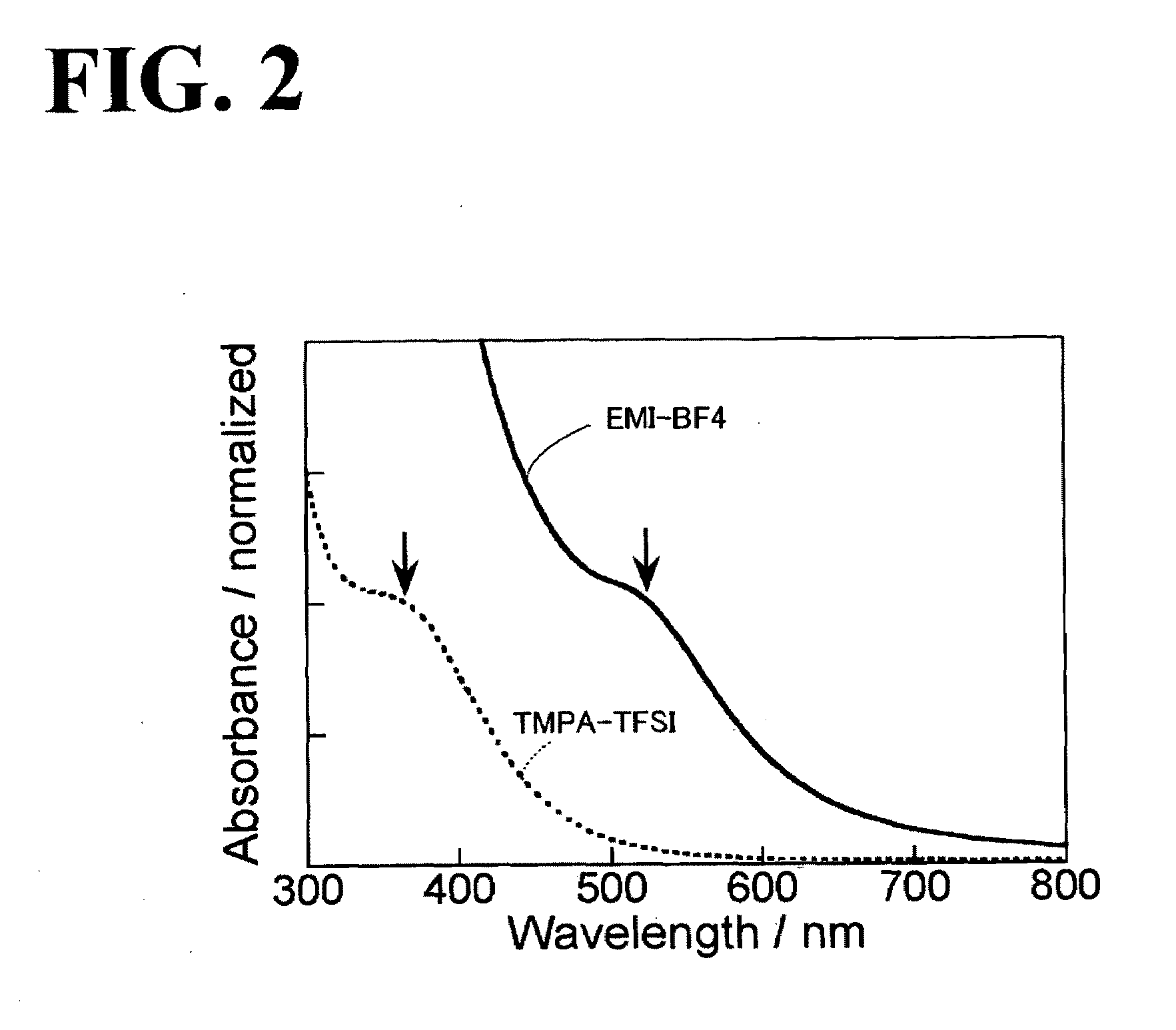
[0035]FIG. 2 illustrates the absorption spectra of the EMI-BF4 solution after the sputtering. In FIG. 2, a solid line indicates the absorption spectrum of the EMI-BF4 solution, and a d...

example 2

[0037](1) Production of Gold Nanoparticles with TMPA-TFSI

[0038]Gold nanoparticles were synthesized as in Example 1, except that N,N,N-trimethyl-N-propylammonium bis(trifluoromethanesulfonyl)imide (TMPA-TFSI) was used as the ionic liquid. After sputtering, the resulting EMI-BF4 solution on the surface of the slide glass was recovered.

(2) Measurement of Absorption Spectrum

[0039]The absorption spectrum of the TMPA-TFSI solution after the sputtering is represented by the dotted line in FIG. 2. In the case of using the TMPA-TFSI as the ionic liquid, the surface plasmon absorption peak of the resulting gold nanoparticles was not observed. An absorption spectrum in which an absorption edge was observed at about 600 nm and the shoulder of the absorption curve was observed at about 350 nm was obtained. It has been reported that for gold nanoparticles having a particle size of about 10 nm or less, a decrease in particle size results in a decrease in surface plasmon peak intensity and a broad ...

example 3

(1) Production of Gold Nanoparticles

[0042]On a slide glass (26 mm×38 mm), 0.60 cm3 of EMI-BF4 was evenly placed. This was placed in an evaporator (JFC-1300, manufactured by JEOL Ltd). A target material composed of gold (a disk with a diameter of 57 mm and a thickness of 0.5 mm) was arranged at a position facing the EMI-BF4, and sputtering was performed with the gold target (evaporation chamber: filled with argon, pressure: 8 Pa, evaporation current: about 40 mA). The sputtering was performed for a reaction time of 0.5 minutes, 1 minute, 2 minutes, or 10 minutes. After the sputtering, the resulting EMI-BF4 solution on the surface of the slide glass was recovered.

(2) Relationship between Reaction Time and Particle Size

[0043]FIG. 6 shows the change in the absorption spectrum of the EMI-BF4 solution after the sputtering at the different reaction times. FIG. 6(b) shows spectra normalized with respect to the absorbance at 400 nm of the spectra shown in FIG. 6(a). As shown in FIG. 6(a), at...


PUM

PropertyMeasurementUnit
particle size distributionaaaaaaaaaa
particle sizeaaaaaaaaaa

Abstract

The present invention provides a method for producing nanoparticles by attaching atoms or molecules constituting a nanoparticle precursor to an ionic liquid. According to this method, it is possible to produce nanoparticles that do not aggregate easily in a liquid without its surface modification. Furthermore, it is possible to produce nanoparticles without the need for a complicated operation or the formation of a by-product because of the direct production of the nanoparticles from the nanoparticle precursor.

Description

TECHNICAL FIELD[0001]The present invention relates to a method for producing nanoparticles.BACKGROUND ART[0002]Known examples of a method for producing nanoparticles in the related art include wet processes in which nanoparticles are produced in solutions using chemical reactions and dry processes in which nanoparticles are directly deposited on substrates using vacuum technology. An example of the wet processes is described in Patent Document 1 which discloses a process for producing copper nanoparticles in a mixed solvent containing an ether solvent and a cyclic ether solvent by adding a copper compound, a stabilizer, and a reducing agent to the mixed solvent and heating the resulting mixture under non-acidic conditions. An example of the dry processes is described in Patent Document 2 which discloses a process for producing gold nanoparticles by vacuum evaporation on a substrate composed of high light-distribution pyrolytic graphite (HOPG) or SiO2. Furthermore, as another vacuum ...

Claims


Application Information

Patent Timeline
Patent Type & Authority Applications(United States)
IPC IPC(8): C07F1/12
CPCB22F9/12B22F9/24B22F2009/245B22F2998/00Y10S977/81B82Y30/00Y10S977/788B22F1/0018B22F1/054
Inventor TORIMOTO, TSUKASAOKAZAKI, KEN-ICHITANAKA, NOBUROKUWABATA, SUSUMU
Owner NAGOYA UNIVERSITY
Why Eureka
Try Eureka