Heat Exchanger

a heat exchanger and heat exchanger technology, applied in the field of ocean thermal energy conversion systems, can solve the problems of reducing the energy necessary to pump primary fluid and/or secondary fluid, and achieve the effects of avoiding the introduction of dissimilar materials at welded joints, reducing the risk of galvanic corrosion, and reducing the risk of corrosion

Active Publication Date: 2009-12-17
LOCKHEED MARTIN CORP
View PDF24 Cites 65 Cited by
  • Summary
  • Abstract
  • Description
  • Claims
  • Application Information

AI Technical Summary

Benefits of technology

[0030]The illustrative embodiment of the present invention is a modular system of components that mate to form a complete heat exchanger core consisting of only a single material. The individual components that compose the heat exchanger are joined together using friction-stir welding; therefore, the introduction of dissimilar materials at welded joints is avoided. As a result, the heat exchanger core is less susceptible to galvanic corrosion. Further, primary and secondary fluids are introduced to the heat exchanger core through manifolds that consist of the same material. The manifolds are also joined to the heat exchanger using friction-stir welding.
[0031]Embodiments of the present invention comprise a plurality of first conduits...

Problems solved by technology

Still further, the low pressure drop through straight conduits reduces the energy ...

Method used


Image

  • Heat Exchanger
  • Heat Exchanger
  • Heat Exchanger

Examples


Embodiment Construction

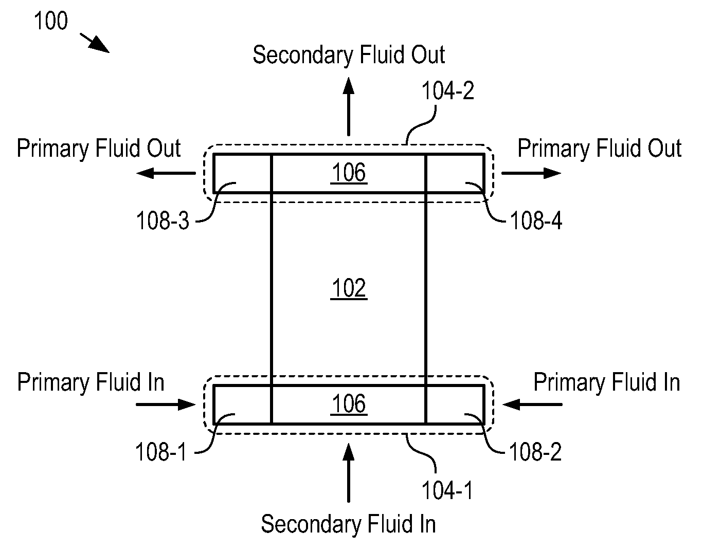
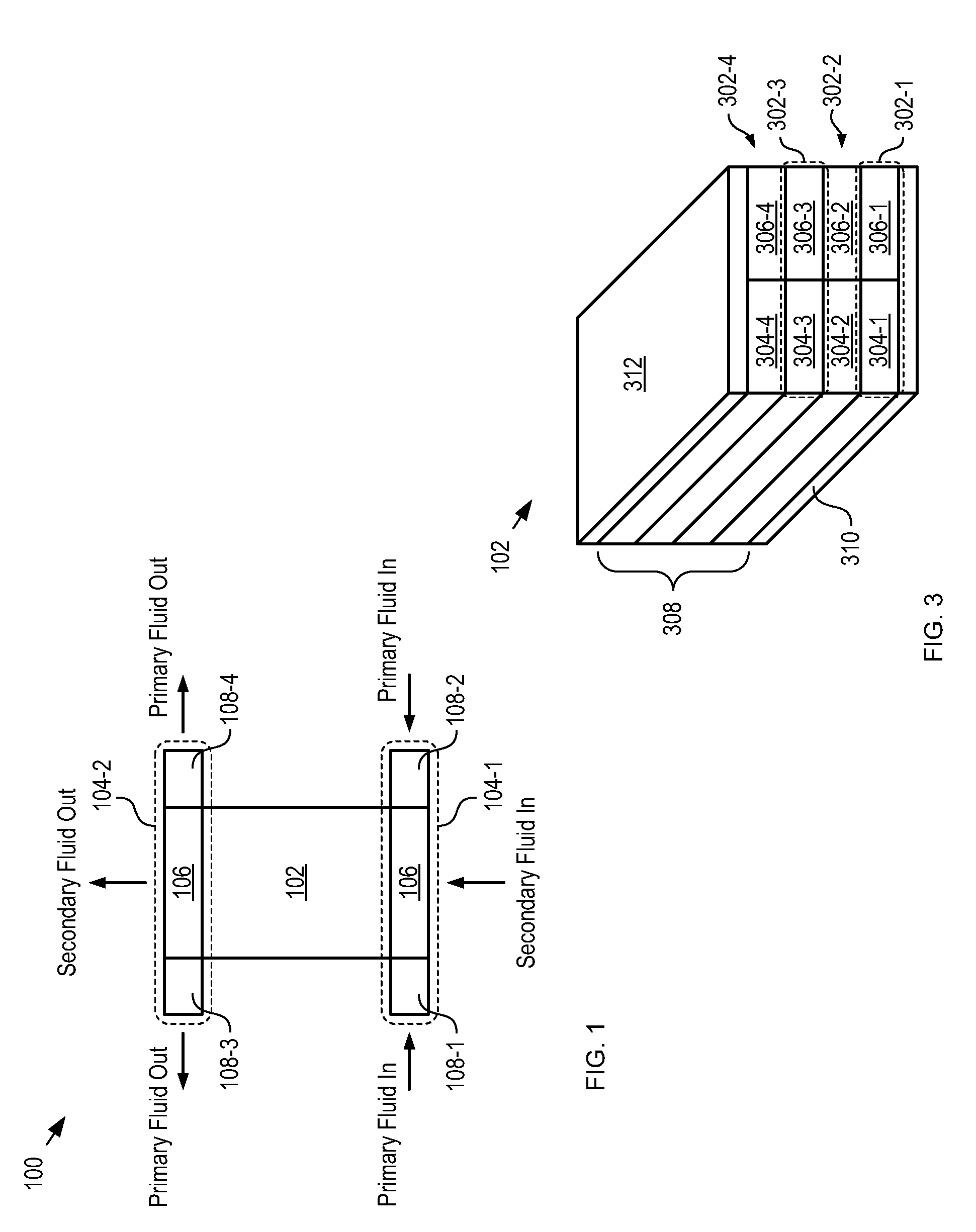
[0050]FIG. 1 depicts a schematic drawing of a heat exchanger in accordance with an illustrative embodiment of the present invention. Heat exchanger 100 comprises heat exchanger core 102 and manifolds 104-1 and 104-2.

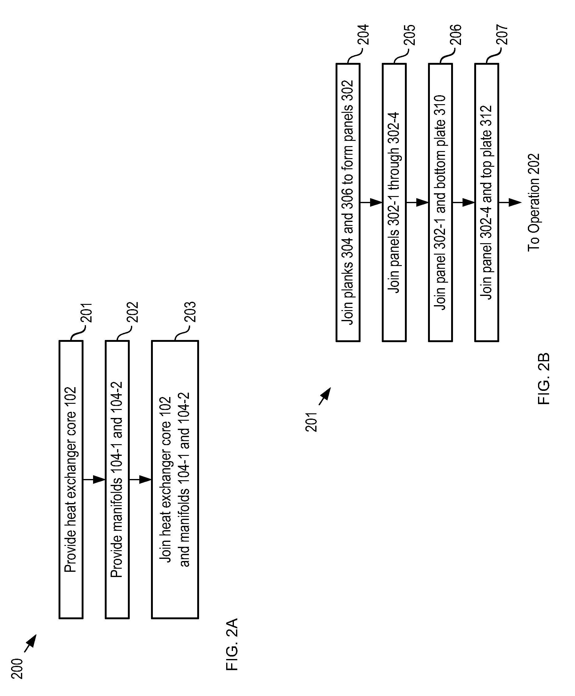
[0051]Heat exchanger core 102 (hereinafter referred to as “core 102”) is a modular system of extruded aluminum planks that are joined together to form a complete core. Core 102 comprises channels through which primary fluid and secondary fluid can flow. As they are conveyed through core 102, heat is transferred between the two fluids. Core 102 is described in more detail below and with respect to FIGS. 3-6.

[0052]Manifolds 104-1 and 104-2 (referred to, collectively, as manifolds 104) provide primary fluid and secondary fluids to the channels of core 102. Each of manifolds 104 comprises ports 108 and distributor 106. Manifolds 104-1 and 104-2 are described in detail below and with respect to FIGS. 6A-C.

[0053]Although the illustrative embodiment comprises components that co...


PUM

PropertyMeasurementUnit
Electrical conductoraaaaaaaaaa
Velocityaaaaaaaaaa

Abstract

A heat exchanger and a method for fabricating the heat exchanger are disclosed. The heat exchanger comprises a heat exchanger core that is formed from a plurality of stacked aluminum panels that are joined together via friction stir welding. Each panel in the core is formed from at least two aluminum extrusions that are joined to one another via friction stir welding.

Description

CROSS REFERENCE TO RELATED APPLICATIONS [0001]This case claims priority to: U.S. Provisional Patent Application Ser. No. 61 / 061,206, filed Jun. 13, 2008 (Attorney Docket: 711-213US) and U.S. Provisional Patent Application Ser. No. 61 / 144,597, filed Jan. 14, 2009 (Attorney Docket: 711-247US); each of which is incorporated by reference.[0002]If there are any contradictions or inconsistencies in language between this application and one or more of the cases that have been incorporated by reference that might affect the interpretation of the claims in this case, the claims in this case should be interpreted to be consistent with the language in this case.FIELD OF THE INVENTION [0003]The present invention relates to ocean thermal energy conversion systems in general, and, more particularly, to a heat exchanger for use in such systems.BACKGROUND OF THE INVENTION [0004]The Earth's oceans are continually heated by the sun and cover nearly 70% of the Earth's surface. The temperature differen...

Claims


Application Information

Patent Timeline
IPC IPC(8): F28F3/08B21D53/08
CPCF28F2275/065Y02E10/34F03G7/05F28F21/084F24J3/08Y10T29/49368Y02E10/10F28F1/045B21D53/02F28F9/0263Y10T29/49384Y10T29/49393B21D53/08F28F2255/16F24T10/00Y02E10/30
Inventor NAGURNY, NICHOLAS J.LEVINGS, NATALIEBECKNER, DEREKELLER, MICHAEL R.GRANDELLI, PATRICK D.RYZIN, JOE VANGOLDSTEIN, ELIOT
Owner LOCKHEED MARTIN CORP
Why Eureka
Try Eureka