Drill bit with replaceable blade members

a technology of replaceable blade members and drill bits, which is applied in the field of drill bits, can solve the problems of increasing problems, insufficient interlocking with the other replaceable blade members, and poor cutting structure of previous drill bits with replaceable blade members, so as to achieve greater strength, better cutting structure coverage, and greater strength

Inactive Publication Date: 2009-12-17
NACKERUD ALAN L
View PDF0 Cites 5 Cited by
  • Summary
  • Abstract
  • Description
  • Claims
  • Application Information

AI Technical Summary

Benefits of technology

[0007]Another object of the present invention is to provide for novel and improved blades which when paired together overlap each other to provide better cutting structure coverage especially near the center of the drill bit.
[0008]A further object of the present invention is to provide for novel and improved replaceable blades which when paired and pinned together provide for greater strength.
[0009]A further object of the present invention is to provide for novel and improved replaceable blades where each pair of blades are interlocked with the additional set of paired blades to provide greater strength.
[0010]A further object of the present invention is to provide for a novel and improved placement of multiple attachment pins between the blades and body that align with the drill bit body in more than one direction for added strength.
[0011]A further object of the present invention is to provide for novel and improved replaceable blades, which due to their overlapping positions can be more easily machined or forged to provide cutting elements with a neutral, positive or negative cutting rake especially at the center of the drill bit.
[0012]A further object of the present invention is to provide for novel and improved replaceable blades which have wedges that can be driven or placed between the blades and the bit body to provide better securing and tightening of the blades to the bit body.

Problems solved by technology

Previous drill bits with replaceable blade members have had poor cutting structure near the center of the drill bit.
They have also been attached or affixed to the body of the drill bit but not sufficiently interlocked with the other replaceable blade members.
The problem presented and which causes the manufacturers to make the drill bits with the negative rake is that the cutter pockets require a small oversize tolerance (e.g. 0.002 inch) for effective brazing and therefore must be machined with a rotating tool which requires a negative rake angle to clear the protruding preceding blade and / or the bottom of the bit.
This problem increases as you move towards the center of the bit.

Method used


Image

  • Drill bit with replaceable blade members
  • Drill bit with replaceable blade members
  • Drill bit with replaceable blade members

Examples


Embodiment Construction

−FORMS FIRST, SECOND, THIRD, AND FOURTH

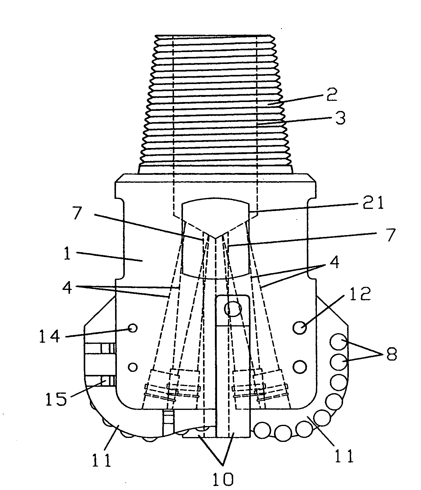
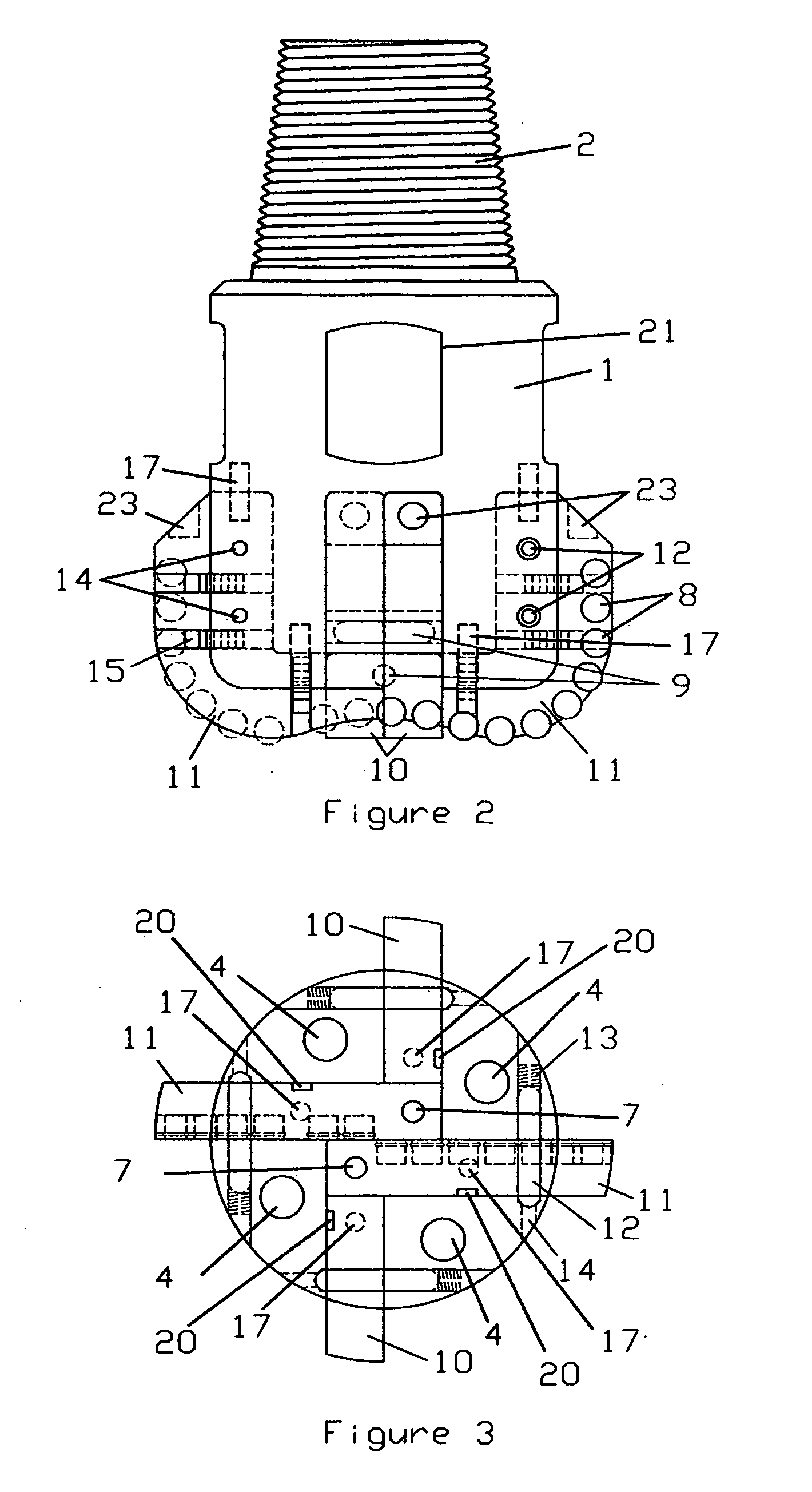
[0058]Referring to the drawings, there is illustrated in FIGS. 1 through 20 four forms of the drill bit assembly. In FIG. 1 (First Form of Drill Bit) the body 1 of the drill bit has a threaded connection 2 on top to allow connection to a drill string. One or more flats 21 are located near the top of the drill bit body 1 to assist in holding the drill bit as it is screwed or unscrewed to the drill string. A main fluid bore 3 runs through the pin connection 2 and into the body 1 where it meets with additional angle bores 4, and optional additional fluid bores 7 which run out through the bottom of the body 1 to provide fluid circulation to remove cuttings and cool the tool. FIG. 1 (First Form of Drill Bit) shows one embodiment of the drill bit with blades 10, 11 affixed to the body 1 by retention pins 9, side pins 12, secondary retention pins 17, and small wedges 15. FIG. 4 (Second Form of Drill Bit) shows another embodiment with blades affixed by...


PUM


Abstract

A drill bit for rotary drilling a well bore of a subterranean formation which has replaceable blades which overlap and interlock with each other and have retention means on more than one axis. The replaceable blades may have cutters with enhanced retention by brazing ring grooves and the body may be flared at its bottom to better retain the blades and cutters.

Description

CROSS-REFERENCE TO RELATED APPLICATIONS[0001]This application claims the benefit of provisional patent application Ser. No. 61 / 131,758 filed Jun. 12, 2008 by Alan L. Nackerud, which is incorporated by reference herein.BACKGROUND AND FIELD OF INVENTION[0002]This invention generally relates to drill bits, specifically to those with replaceable blade members.[0003]Previous drill bits with replaceable blade members have had poor cutting structure near the center of the drill bit. They have also been attached or affixed to the body of the drill bit but not sufficiently interlocked with the other replaceable blade members.[0004]Most conventional PDC (Polycrystalline Diamond Cutter) or other hardened material fixed cutter drill bits are machined or forged with fixed integral body protruding blades having cutters inserted with a negative or back rake. This allows manufacturers to machine the pockets. The problem presented and which causes the manufacturers to make the drill bits with the ne...

Claims


Application Information

Patent Timeline
Patent Type & Authority Applications(United States)
IPC IPC(8): E21B10/627
CPCE21B10/627
Inventor NACKERUD, ALAN L.
Owner NACKERUD ALAN L
Why Eureka
Try Eureka