Multi-color biosensor

a biosensor and multi-color technology, applied in the field of optical detection, can solve the problems of difficult to find, difficult to realize, and difficult to realize, and achieve the effects of reducing the overall analysis time, cost-effective production, and robust detection system

Inactive Publication Date: 2009-12-17
KONINKLIJKE PHILIPS ELECTRONICS NV
View PDF7 Cites 55 Cited by
  • Summary
  • Abstract
  • Description
  • Claims
  • Application Information

AI Technical Summary

Benefits of technology

[0006]Signal isolation and data analysis are facilitated by maximizing the spectral separation of the multiple emissions. Consequently, fluorophores with narrow spectral bandwidths are particularly useful in multicolor applications. An ideal combination of dyes for multicolor labeling would exhibit strong absorption at a coincident excitation wavelength and well-separated emission spectra. There is a need for single dyes with the requisite combination of a large extinction coefficient for absorption and a large wavelength (Stokes) shift. These are difficult to find. Moreover, multiple wavelengths focusing often implies expensive and complicated optical systems such as imaging lens assemblies, movable parts to bring the sample in focus such as in microscopes, or tilting parts.
[0023]It is an advantage of particular embodiments of the present invention that parts of the biosensor can be obtained from existing mass-produced, low-cost optical pick-up units allowing to obtain detection systems in a cost effective manner.

Problems solved by technology

At present, simultaneous multi-color detection is severely restricted by the limitations of current optical detection devices, or by the costs involved.
These are difficult to find.
Moreover, multiple wavelengths focusing often implies expensive and complicated optical systems such as imaging lens assemblies, movable parts to bring the sample in focus such as in microscopes, or tilting parts.

Method used


Image

  • Multi-color biosensor
  • Multi-color biosensor
  • Multi-color biosensor

Examples


second embodiment

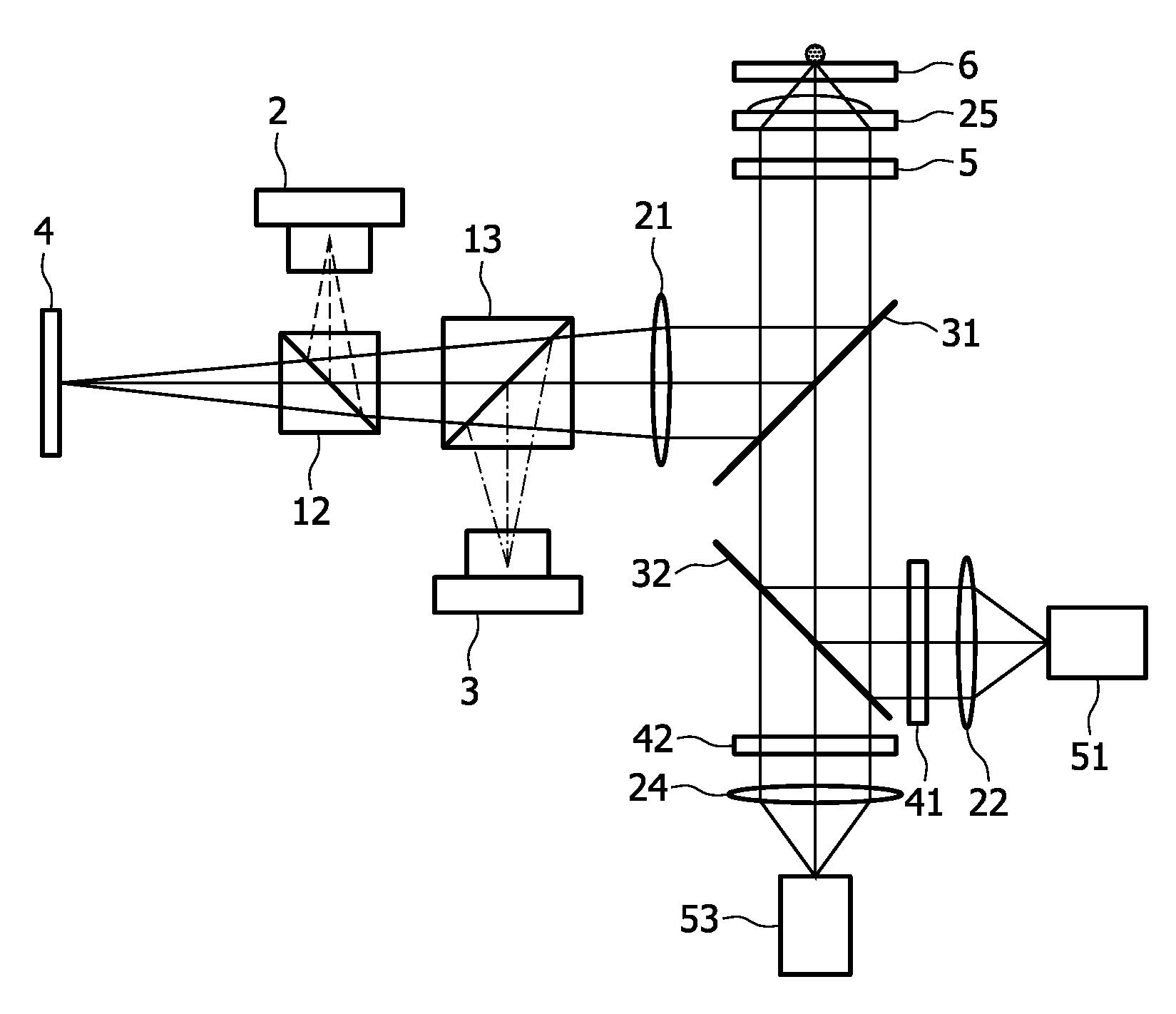
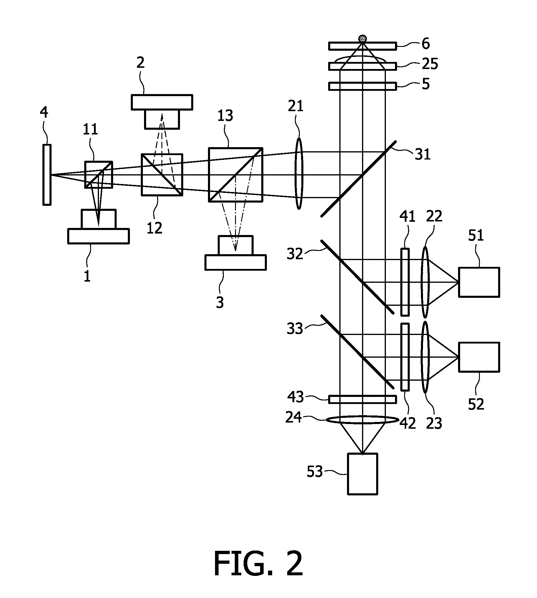
[0059]A second embodiment according to the first aspect of the present invention relates to a detection system as described above, wherein only a single excitation irradiation beam is used, but wherein the optical element 25, e.g. refractive element, used for focusing the single excitation irradiation beam on the substrate is also used for collecting at least one luminescence irradiation beam having a different wavelength than the excitation irradiation beam. The detection system thereby comprises an optical compensator for adjusting at least one of the excitation irradiation beam or the luminescence irradiation beam(s) for optical aberrations induced by the optical element, e.g. refractive element. The second embodiment will be illustrated using an example, the invention not being limited thereto. According to an exemplary detection system as shown in FIG. 5, a single excitation irradiation beam is used to excite the sample 6 and at least one, e.g. two different luminescence irrad...


PUM


Abstract

A detection system is described (100) for detecting luminescence sites on a substrate (6). The detection system (100) typically comprises an irradiation unit (102) for generating at least one excitation irradiation beam for exciting luminescence sites on the substrate (6). The at least one excitation irradiation beam may be a plurality of excitation irradiation beams. The detection system (100) also comprises a first optical element, e.g. refractive element (25), adapted for receiving at least two irradiation beams of different wavelengths or wavelength ranges, the at least two irradiation beams being excitation irradiation beam(s) to be focused on a substrate and / or luminescence irradiation beam(s) to be collected from the excited luminescence sites on the substrate (6). The detection system (100) also comprises an optical compensator for adjusting at least one of the at least two irradiation beams of different wavelengths or wavelength ranges so as to reduce or compensate for optical aberrations. The present invention also relates to a corresponding method for detecting, a phase plate and a method for designing such a phase plate.

Description

FIELD OF THE INVENTION[0001]The present invention relates to the field of optical detection. More particularly, the present invention relates to methods and systems for optical detection such as detection of luminescent signals, e.g. as used in qualitative or quantitative detection of biological, chemical or bio-chemical analysis, e.g. using particles or fluorophores, and to means for improving such detection methods and systems.BACKGROUND OF THE INVENTION[0002]An image reading apparatus is described (U.S. Pat. No. 6,617,590) which includes three laser sources, a scanning mechanism for scanning a surface with a laser beam emitted from the laser sources, a light detector and a confocal optical system for leading light emitted from the image carrier to the light detector. The apparatus makes provision for a number of relevant detection techniques such as microarray imaging, autoradiographic imaging, chemiluminescent imaging and more. It includes a confocal switching member having pinh...

Claims


Application Information

Patent Timeline
Patent Type & Authority Applications(United States)
IPC IPC(8): G01J1/58G02B27/16
CPCG01J3/02G01J3/021G01J3/10G01J3/36G01J3/4406G01N2021/6463G01N21/645G01N2021/6419G01N2021/6421G01N2021/6441G01N21/6428
Inventor VAN DIJK, ERIK MARTINUS HUBERTUS PETRUSBOAMFA, MARIUS IOSIFWIMBERGER-FRIEDL, REINHOLD
Owner KONINKLIJKE PHILIPS ELECTRONICS NV
Why Eureka
Try Eureka