Method of detecting moving objects

a technology of moving objects and methods, applied in the field of detection methods, can solve the problems of limiting the use of related algorithms, unable to efficiently overcome environmental factors, and affecting the effect of noise rejection ability, and so as to achieve the effect of reducing the loading of the system, and simplifying the related calculation process

Inactive Publication Date: 2009-12-17
HUPER LAB
View PDF6 Cites 92 Cited by
  • Summary
  • Abstract
  • Description
  • Claims
  • Application Information

AI Technical Summary

Benefits of technology

[0017]The active contour-based tracking method, in which a moving object is expressed by its contour, involves endowing the contour of the moving object with characteristics of an image space, such as image edge or shape. Subsequently, the contour of the moving object may be updated based on the extracted image information for tracking the moving object. Since this method only extracts the contour of the moving object instead

Problems solved by technology

However, signal decay and noise disturbance may occur during the information transmission, and various environmental factors, such as ambient light influence on cameras, limit the use of the related algorithms.
This is a simple and efficient method, but it cannot efficiently overcome some environmental factors, such as light variation, noise disturbance, shadow variation, camera vibration, and so on.
The said method has good robustness for environmental variation, but is incapable of detecting the moving object when it stops moving temporarily.
However, unobservable motion and false motion may not be detected and processed efficiently in this method.
The so-called unobservable motion means that no obvious brightness variation appears inside a moving object so that the real motion of the moving object cannot be detected by the optic flow method.
And, the false motion means that a wrong motion vector of a motionless object may be detected by the optic flow method when color information of the motionless object changes with sudden light variation.
Furthermore, number of calculations performed in the optic flow method is very high, since the related mathematic operations are performed on every pixel, and the optic flow method is very sensitive to noise disturbance and light variation in

Method used


Image

  • Method of detecting moving objects
  • Method of detecting moving objects
  • Method of detecting moving objects

Examples


Embodiment Construction

[0034]The present invention involves utilizing a real-time system to extract traffic parameters. The main method is to extract features of the moving vehicle via image processing technology so as to know vehicle states in a surveillance area. Subsequently, the necessary traffic parameters may be further provided to post processing of the ITS.

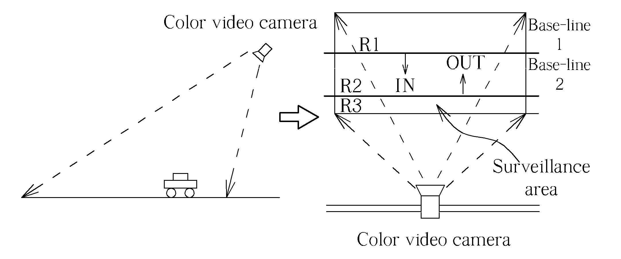
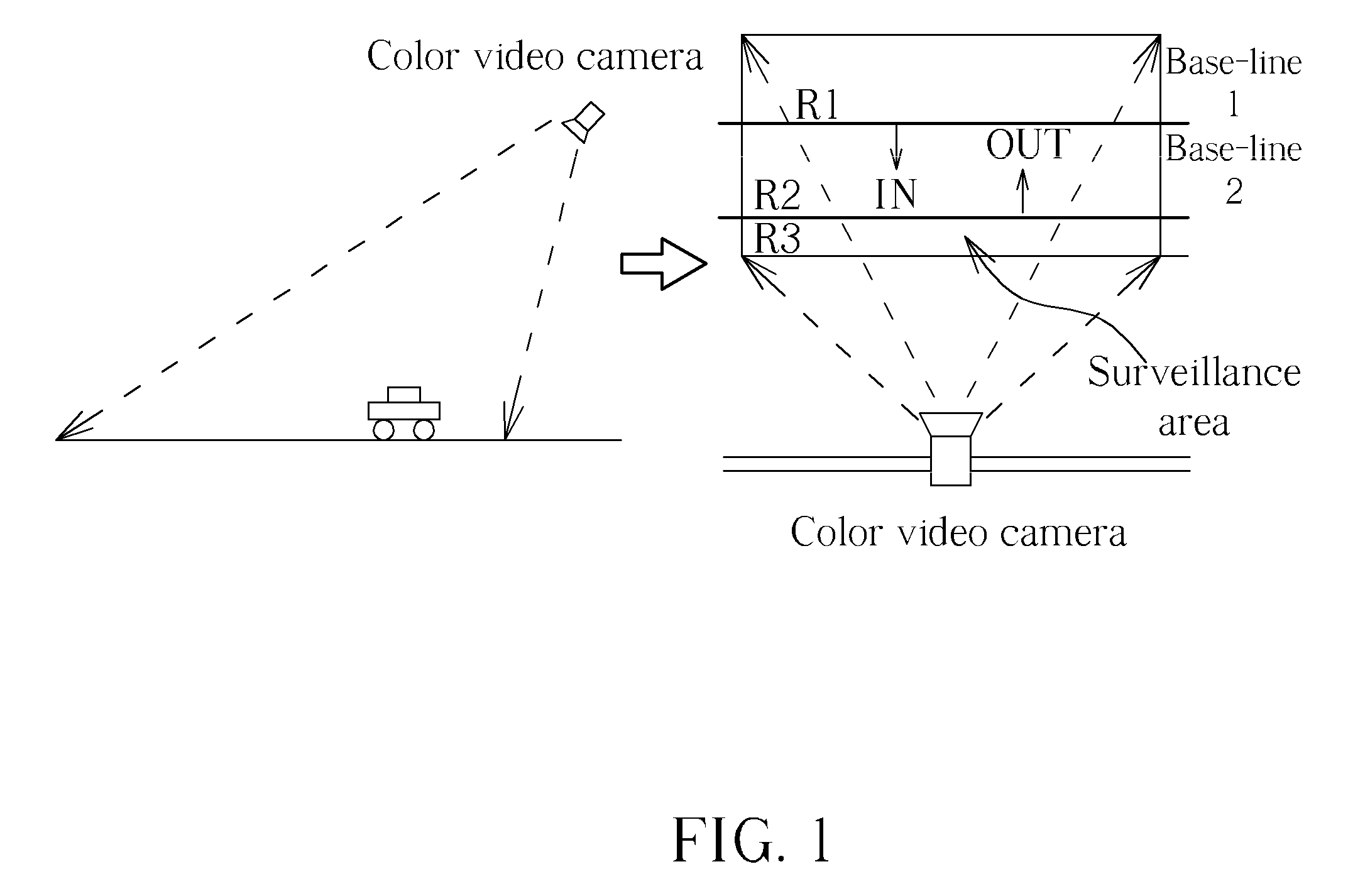
[0035]Please refer to FIG. 1. The major objective of a real-time vehicle-flow analyzing and counting system according to the present invention is application to a traffic-surveillance system. Therefore, a surveillance camera setup scheme in the present invention is like a common camera setup scheme on a road for capturing vehicle-flow images, and two base-lines are set in the said images for detecting moving directions of vehicles and extracting vehicle-flow data.

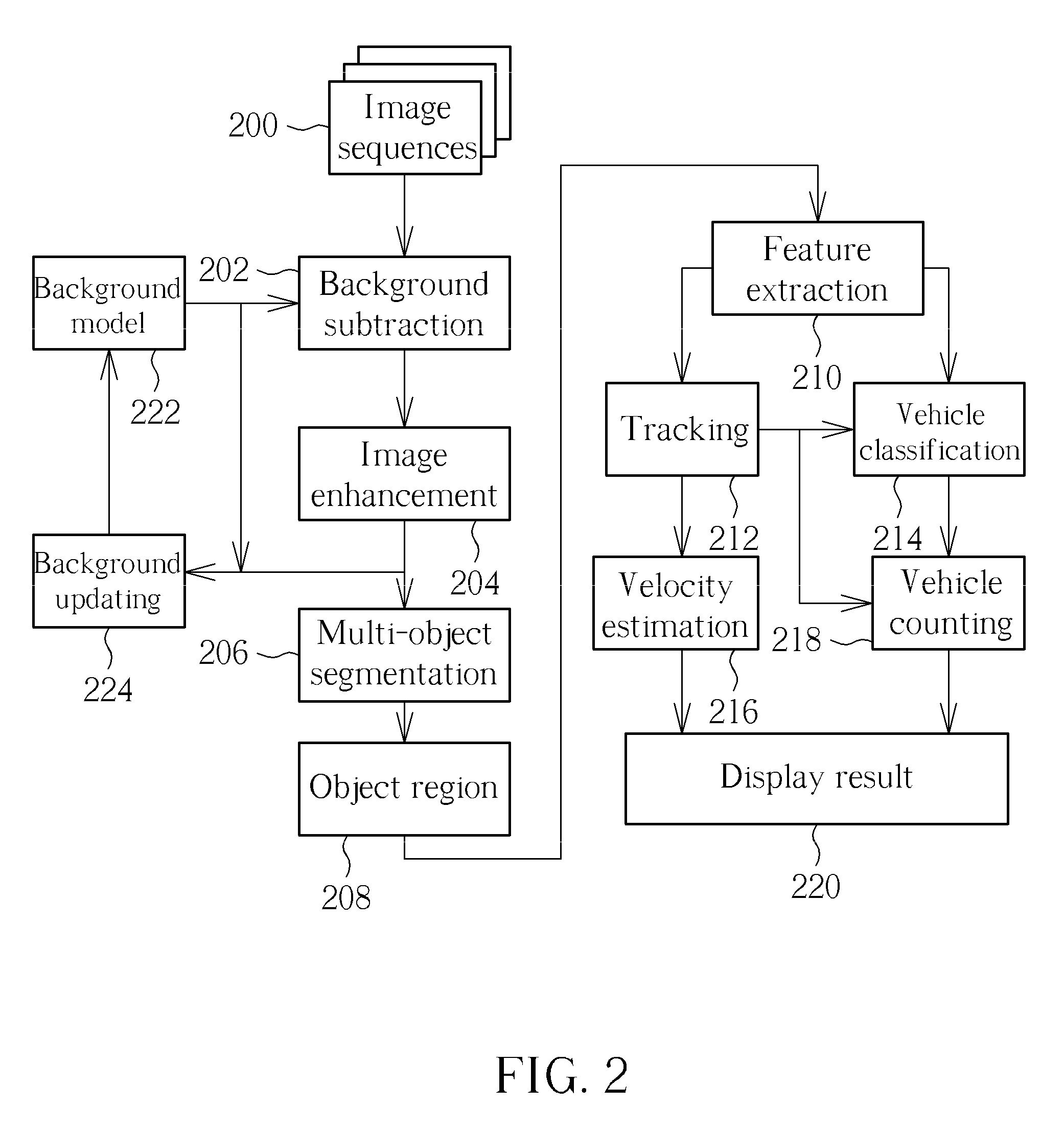
[0036]Next, please refer to FIG. 2. The method of the present invention may be divided into three procedures: moving object detection, vehicle classification, and vehicle-tracking. The ...


PUM


Abstract

A method for detecting moving objects includes: (a) capturing and establishing a background image; (b) capturing at least one current image; (c) transforming the background image and the current image from an RGB color format into an HSI color format; (d) subtracting the background image from the current image according to a background subtraction rule for generating at least one moving object; (e) performing a vertical scanning and a horizontal scanning on the moving object for generating a minimum bounding box of the moving object; (f) calculating a characteristic datum of the moving object according to the minimum bounding box; (g) tracking the moving object according to the characteristic datum with a Euclidean distance rule; (h) classifying the moving object according to the characteristic datum, the tracking result generated by step (g) and a minimum distance classifier.

Description

BACKGROUND OF THE INVENTION[0001]1. Field of the Invention[0002]The present invention relates to a detecting method, and more specifically, to a method of detecting moving objects.[0003]2. Description of the Prior Art[0004]In recent years, traffic surveillance systems have been put forward extensively for discussion and study because they provide meaningful and useful information, such as data on speed limit violations and other traffic infractions. An ITS (Intelligent Transportation System) is one of the most representative examples. The ITS integrates communication, control, electronic, and information technologies to make most efficient use of limited transportation resources to increase quality of life and economic competitiveness.[0005]The ITS technology comprises microelectronics, automatic artificial intelligence, sensors, communications, control, and so on. Another important technology is computer vision. Since efficient operation of the ITS depends on accurate real-time tra...

Claims


Application Information

Patent Timeline
IPC IPC(8): H04N7/18
CPCG06T7/20G06T7/2046G06T2207/30248G06T2207/30236G06T2207/10016G06T7/251
Inventor CHEN, CHAO-HOLIN, YU-FENG
Owner HUPER LAB
Why Eureka
Try Eureka