Liquid crystal display and driving method thereof

a technology of liquid crystal display and driving method, which is applied in the direction of electric digital data processing, instruments, computing, etc., can solve the problems of overheating of the driving circuit, increasing the consumption of electric power, and not meeting the user's requirements, so as to reduce heating and consumption electric power

Active Publication Date: 2009-12-17
LG DISPLAY CO LTD
View PDF11 Cites 53 Cited by
  • Summary
  • Abstract
  • Description
  • Claims
  • Application Information

AI Technical Summary

Benefits of technology

[0026]An advantage of the present invention is to provide a liquid crystal display device and a method for driving thereof that reduces the heating and the consumption electric power of the data driving circuit.
[0027]Additional features and advantages of the invention will be set forth in the description which follows, and in part will be apparent from the description, or may be learned by practice of the invention. The objectives and other advantages of the invention will be realized and attained by the structure particularly pointed out in the written description and claims hereof as well as the appended drawings.
[0028]To achieve these and other advantages and in accordance with the purpose of the present invention, as embodied and broadly described, a liquid crystal display panel includes: a liquid crystal display panel including a plurality of data lines crossing a plurality of gate lines and liquid crystal cells arranged in a matrix; a timing controller generating a polarity control signal, deciding if a predetermined weak pattern data is input, and shifting a phase of the polarity control signal in a next frame period following a frame showing the weak pattern data when the weak pattern data is input; a data driving circuit reversing the polarity of the data voltage in response to the polarity control signal and supplying to the data lines; and a gate driving circuit supplying a gate pulse to the gate lines sequentially.
[0029]In another aspect of the present invention, a liquid crystal display panel according to another exemplary embodiment includes: a liquid crystal display panel including a plurality of data lines crossing a plurality of gate lines and liquid crystal cells arranged in a matrix; a timing controller generating a polarity control signal, deciding if a predetermined weak pattern data and a DC image sticking data are input, and shifting a phase of the polarity c

Problems solved by technology

When the polarity of data voltage is alternated, the swing width of data voltage supplied to the data lines is large and the data driving circuit requires large electric current so that the data driving circuit is overheated and the consumption electric power will be increased.
However, the effect of this technique is not sufficiently met to the user's requirements.
However, as the swing width of t

Method used


Image

  • Liquid crystal display and driving method thereof
  • Liquid crystal display and driving method thereof
  • Liquid crystal display and driving method thereof

Examples


first embodiment

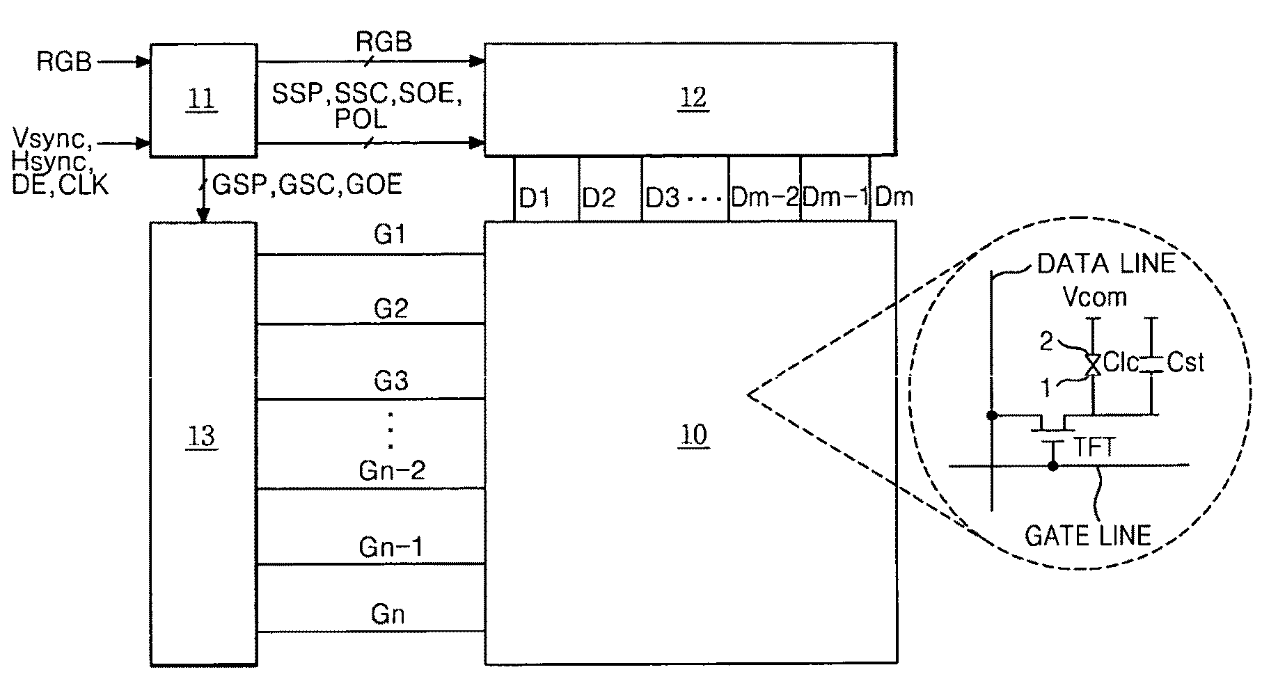
[0058]Referring to FIG. 10, the liquid crystal display device according to the present disclosure includes a liquid crystal display panel 10, a timing controller 10, a timing controller 11, a data driving circuit 12, and a gate driving circuit 13.

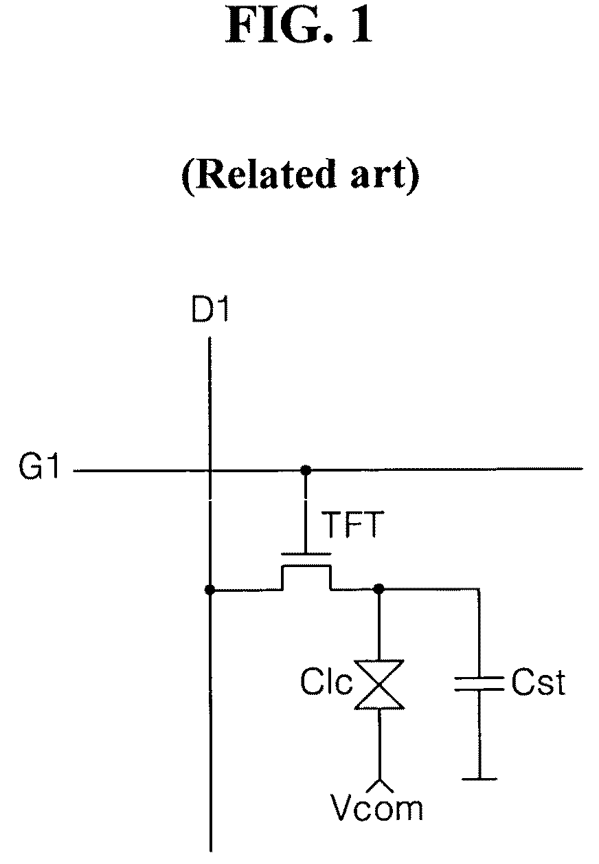
[0059]The liquid crystal display panel 10 includes two glass substrates joining each other and a liquid crystal layer there between. On the lower glass substrate of the liquid crystal display panel 10, data lines (D1 to Dm) and gate lines (G1 to Gn) are disposed crosswisely each other. The liquid crystal cells (Clc) are disposed in a matrix pattern of m×n on the liquid crystal display panel 10 having the crosswise structure of the data lines (D1 to Dm) and the gate lines (G1 to Gn).

[0060]On the lower glass substrate of the liquid crystal display panel 10, data lines (D1 to Dn), gate lines (G1 to Gn), TFTs at the area crossing the data lines and the gate lines, pixel electrodes of each liquid crystal cells (Clc) connected to TFTs, and storag...

second embodiment

[0085]FIG. 16 illustrates a liquid crystal display device according to the present disclosure.

[0086]Referring to FIG. 16, the liquid crystal display device according to the second embodiment of the present disclosure includes a liquid crystal display panel 20, a timing controller 21, a data driving circuit 22, and a gate driving circuit 23.

[0087]The liquid crystal display panel 20 and the gate driving circuit 23 of the second embodiment are the same with those of the first embodiment, so that detail explain about them will not be mentioned.

[0088]The timing controller 21 receives timing signals such as the vertical synchronizing signal (Vsync), the horizontal synchronizing signal (Hsync), the data enable signal (DE), and the dot clock (CLK), and generates the data timing control signal and the gate timing control signal, and then supplies the digital video data (RGB) to the data driving circuit 22. The gate timing signal is the substantially same as that of the first embodiment. The ...


PUM


Abstract

The exemplary embodiment relates to a liquid crystal display device and a driving method thereof for reducing heat and electric consumption power of the data driving circuit. The exemplary embodiment includes: a liquid crystal display panel including a plurality of data lines crossing a plurality of gate lines and liquid crystal cells arranged in a matrix e; a timing controller generating a polarity control signal, deciding if a predetermined weak pattern data is input, and shifting a phase of the polarity control signal in a next frame period following a frame showing the weak pattern data when the weak pattern data is input; a data driving circuit reversing the polarity of the data voltage in response to the polarity control signal and supplying to the data lines; and a gate driving circuit supplying a gate pulse to the gate lines sequentially.

Description

[0001]This application claims the benefit of Korean Patent Application No. 10-2008-0055419 filed on Jun. 12, 2008, which is incorporated herein by reference for all purposes as if fully set forth herein.BACKGROUND OF THE INVENTION[0002]1. Field of the Invention[0003]The present invention relates to a liquid crystal display device (or “LCD device”). Especially, the exemplary embodiment relates to a liquid crystal display device and a driving method thereof for reducing heat and electric consumption power of the data driving circuit.[0004]2. Discussion of the Related Art[0005]The liquid crystal display device presents video images by controlling the light transparent ratio of the liquid crystal cells according to the input video signals. The active matrix type liquid crystal display device controls the video data actively by switching the voltage of the video data supplied to the liquid crystal cells using thin film transistors (TFTs) disposed at each liquid crystal cells (Clc) as sho...

Claims


Application Information

Patent Timeline
IPC IPC(8): G02F1/1345G09G3/36
CPCG09G3/3614G09G3/3648G09G3/3688G09G2310/0248G09G2310/027G09G2360/16G09G2320/0233G09G2320/0613G09G2330/021G09G2330/023G09G2320/0219G09G3/36G09G3/20G02F1/133
Inventor KIM, JINSUNGJANG, SUHYUK
Owner LG DISPLAY CO LTD
Why Eureka
Try Eureka