[0025]An important
advantage of the present invention can be found in scenarios where a particular joining line in the precoding group changes from an inactive line to an active line. Joining lines introduce new crosstalk on active lines which means that their influence on the other lines has to be determined and eliminated by precoding before the joining line begins normal full-
power transmission. Otherwise, the joining line may interrupt active lines or reduce the
signal quality of active lines significantly.
[0026]It is therefore beneficial to find ways to estimate crosstalk from a joining line quickly, so that the joining line can quickly begin normal full-
power transmission without harming other lines. To obtain the shortest
delay, it is beneficial to select a subset of K=1 line where that
single line is the joining line. For a subset of K=1, the pilot sequence is of length L=2 which means that the
delay to estimate the crosstalk of that particular joining line on other lines is reduced to the transmission of only two symbols. Even if all lines in the preceding group are taken into consideration when determining the crosstalk information, thus feedback information is received and used from each line in the precoding group except the joining line which is transporting the pilot sequences, this reduces the computational requirements and time required for the computation of crosstalk information significantly. This means that repeated measurements, each consisting of error feedback from L=2 symbols, can be performed on the joining line during initialization. Repeated measurements in a smaller time-frame have as a result that the power at which the joining line is allowed to operate can increase at a higher rate than in a situation where longer sequences are used, for example as would be necessary if unique orthogonal pilot sequences are sent on all communication lines.
[0027]The error feedback measurement on lines may be something which is performed automatically or which may be coordinated. In certain embodiments, a
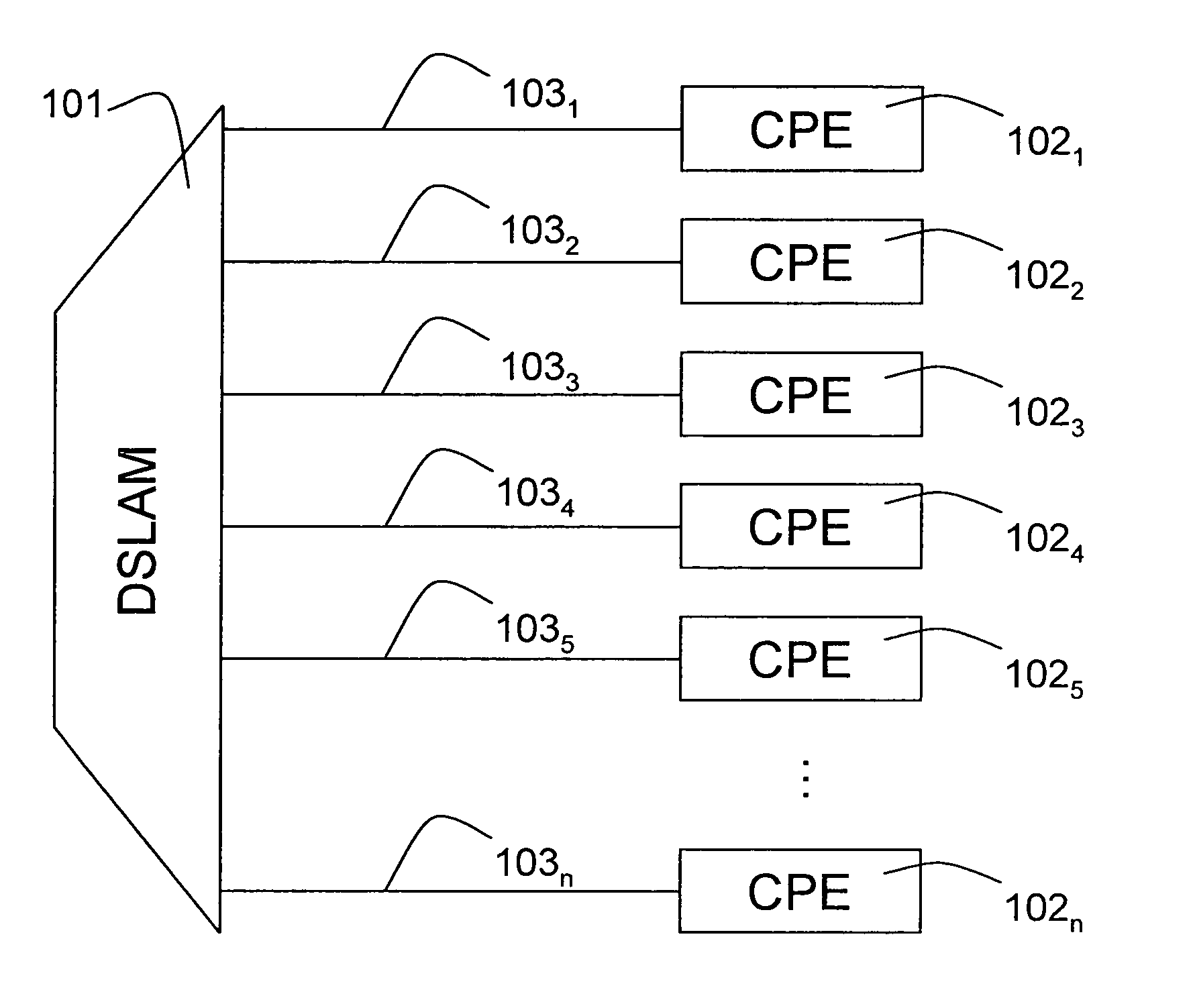
receiver such as a CPE may always perform measurements on received signals and provide error feedback to a
transmitter such as a DSLAM based on those measurements. The
receiver or CPE may perform those measurements on every signal or on particular signals or symbols. However a
transmitter or DSLAM may instruct the receiver or CPE to perform error measurements on a certain signal or symbol for a particular period of time or number of symbols or until the DSLAM instructs the receiver or CPE to stop measurements. In case of measurements which are performed continuously on particular symbols and error being fed back as soon as the measurement has ended, a DSLAM is able to determine crosstalk information by simply initiating the transmission of pilot sequences as the error feedback will be available anyway. Due to the potential high number of CPE's or receivers connected to a DSLAM or
transmitter, sending instructions to each CPE may introduce a large load on the DSLAM to coordinate the instructions and introduces additional load on the communication lines whereon the instructions are transmitted. The error feedback information may be transmitted back as soon as it is available or may be collected at the CPE side until all measurements are performed. The
advantage of feedback as soon as available is that each error feedback communication requires a small piece of the available bandwidth on the communication line whereas sending all the data back in a single transmission may require a higher peak bandwidth. The DSLAM may be able to request the error feedback information from the CPE or the CPE may deliver the information to the DSLAM automatically.
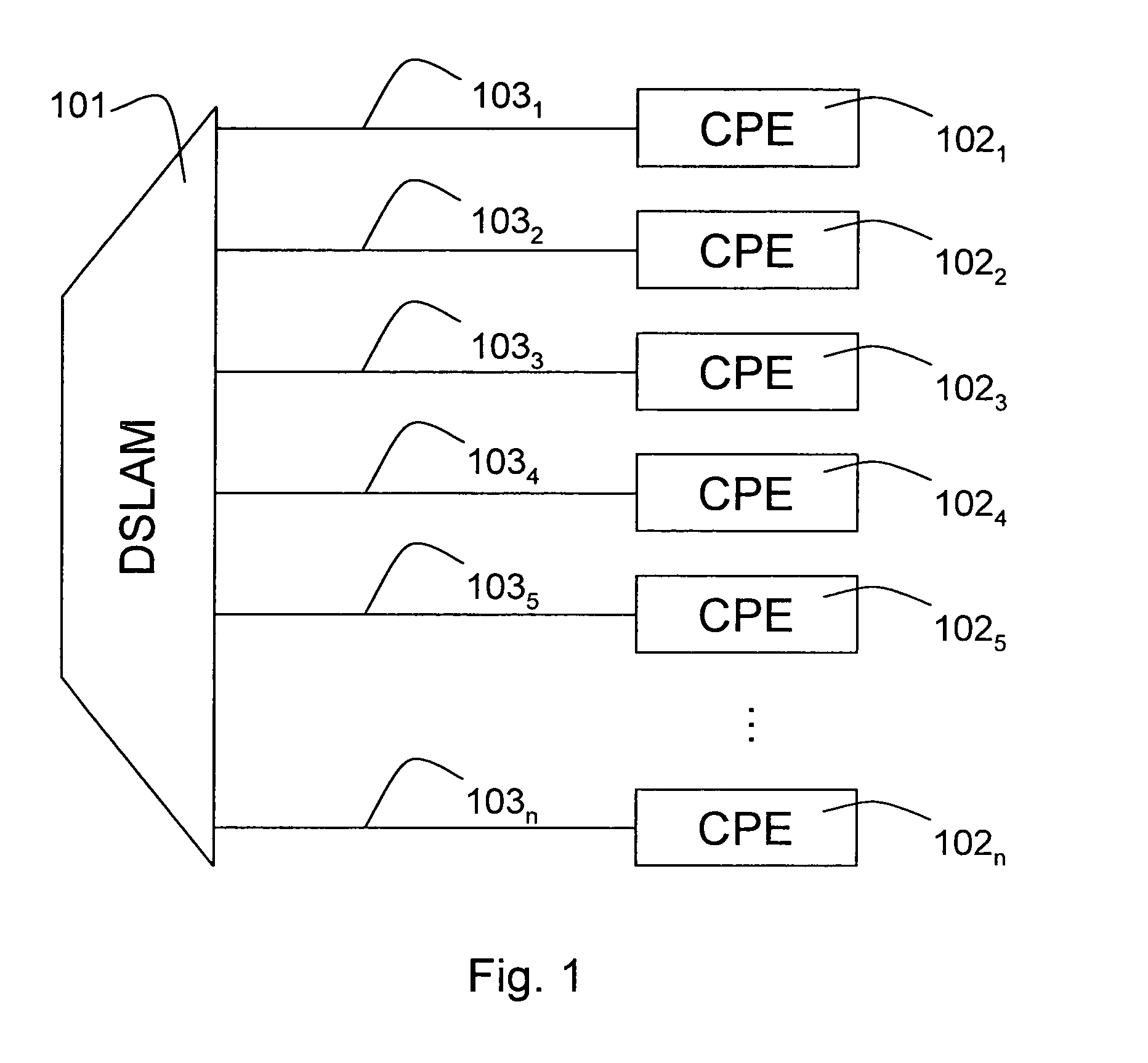
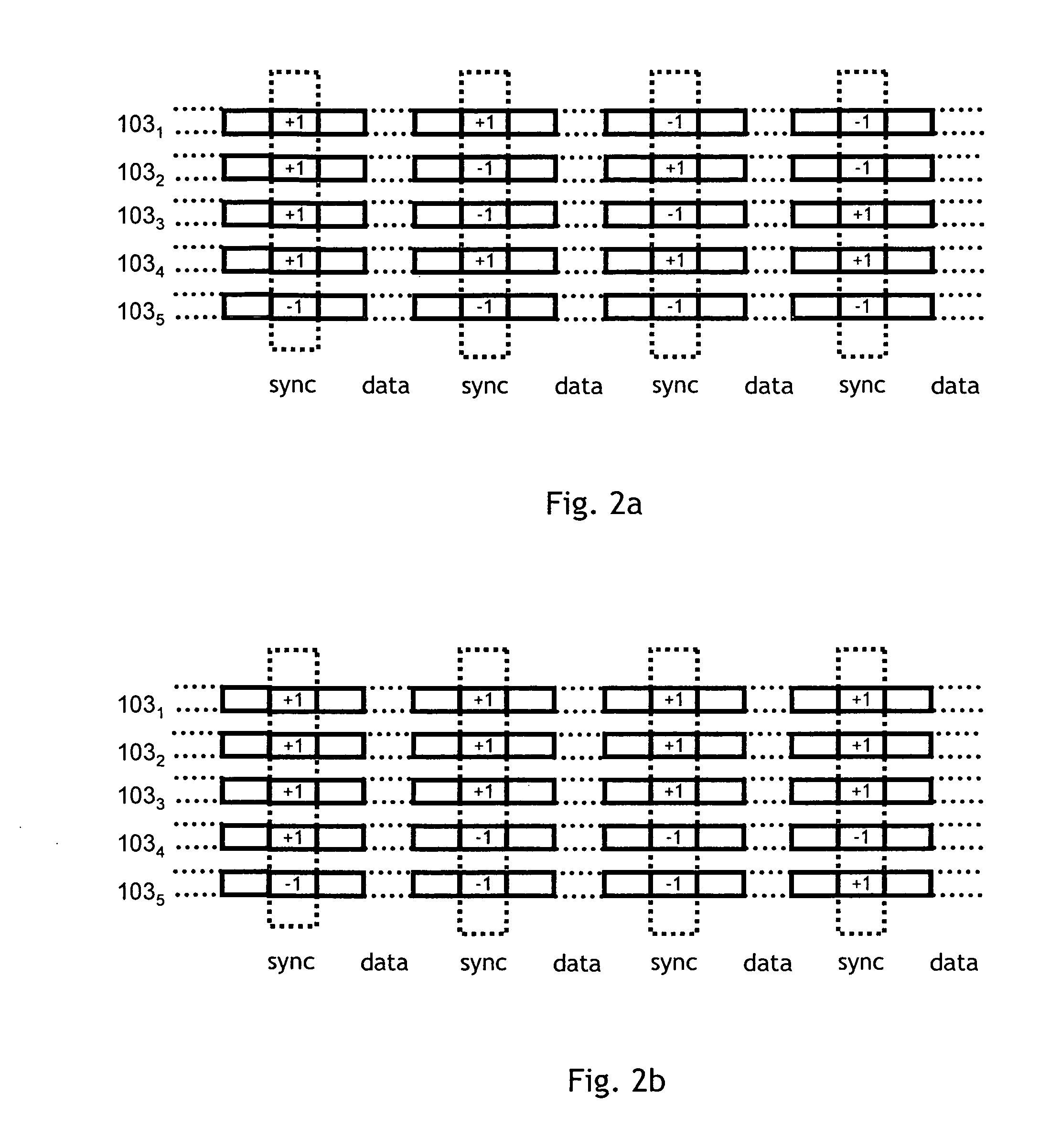
[0028]It is important to realize that in view of the present invention, signals which are transported on communication lines which are not part of the subset are not considered pilot sequences. Communication lines which are not part of the selected subset typically will also transport a particular signal while the lines in the subset transport their pilot sequence. For instance where pilot sequences are transported in the
sync symbol on each line, the lines of the precoding group not part of the subset may transport a symbol in their
sync symbol. Of course, care should be taken to ensure that the signals transported in the sync symbol on lines not in the subset are distinguishable from those used in the pilot sequences. When pilot sequences are equal to or are strongly correlated with the signals transported in the sync symbols of lines not in the subset, it is difficult or impossible to accurately estimate crosstalk coefficients from lines in the subset, using error feedback. On the other hand, when pilot sequences are orthogonal to the signals transported in the sync symbols of lines not in the subset, these latter signals do not interfere at all with the ability to estimate crosstalk coefficients from lines in the subset, using error feedback.
[0029]Optionally the crosstalk estimation device according to the present invention may further comprise means for estimating crosstalk based on a correlation between the error feedback and the pilot sequence.
[0030]The device which transmits the pilot sequences such as a DSLAM is aware of the transmitted pilot sequences. By receiving the error feedback information from the device which receives the pilot sequences such as a CPE, the device is able to determine the crosstalk coefficients of the crosstalk channels between the lines whereon pilot sequences are transmitted and the lines wherefrom error feedback information is used. The crosstalk coefficients can be determined based on a correlation between the transmitted pilot sequence and the received error feedback. The correlation ensures that an exact estimation of the crosstalk coefficients is obtained and that the crosstalk channels are characterized accurately. Such accurate information can then be used to adapt the preceding in order to substantially eliminate interference from existing crosstalk channels.

