Antenna device for use in vehicle

a technology for vehicle antennas and antennas, which is applied in the direction of antenna details, instruments, antennas, etc., can solve the problems of deterioration of measurement accuracy of each of the two devices, compromising the measurement accuracy of each of the dcm and the navigation apparatus, and preventing the deterioration of the signal quality of the gps signal

Active Publication Date: 2009-09-10
DENSO CORP
View PDF4 Cites 0 Cited by
  • Summary
  • Abstract
  • Description
  • Claims
  • Application Information

AI Technical Summary

Benefits of technology

[0025]In other words, in the present disclosure, in view of this particular difference of the operation conditions, by switching the signal transmission route of the GPS signal from the GPS antenna element to the second terminal, the deterioration of the signal quality of the GPS signal is prevented for both of the navigation apparatus and the communication device.

Problems solved by technology

Therefore, both of the two GPS antenna elements for the DCM and for the navigation apparatus are disposed at close positions in one package, with compromise, by allowing the performance deterioration, because the antenna integration of combining these different types of antennas in one package deteriorates, so far, the performance of the antenna due to the interference between the two GPS antenna elements using the same frequency band.
In this case, the C / N (Carrier-Noise) ratio of the GPS signals to be input respectively to the navigation apparatus and the communication device (i.e., the DCM) is deteriorated, thereby compromising the measurement accuracy of each of the DCM and the navigation apparatus.
However, the shared use of the single GPS antenna element by the different devices leads to the distribution loss that also deteriorates the input level of the GPS signal for each of the two devices if the GPS signal is simply distributed to the two devices, thereby causing the compromise and the deterioration of measurement accuracy of each of the two devices.

Method used


Image

  • Antenna device for use in vehicle
  • Antenna device for use in vehicle
  • Antenna device for use in vehicle

Examples


Embodiment Construction

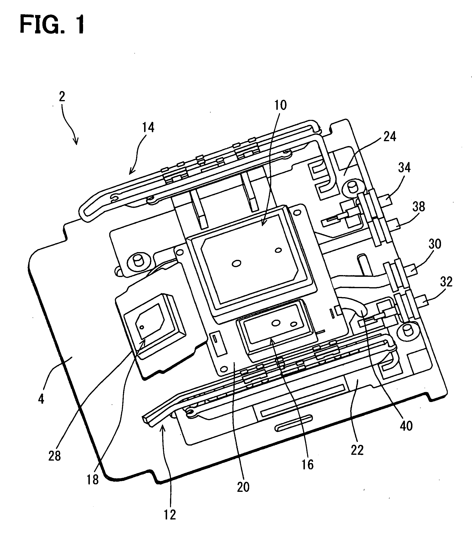
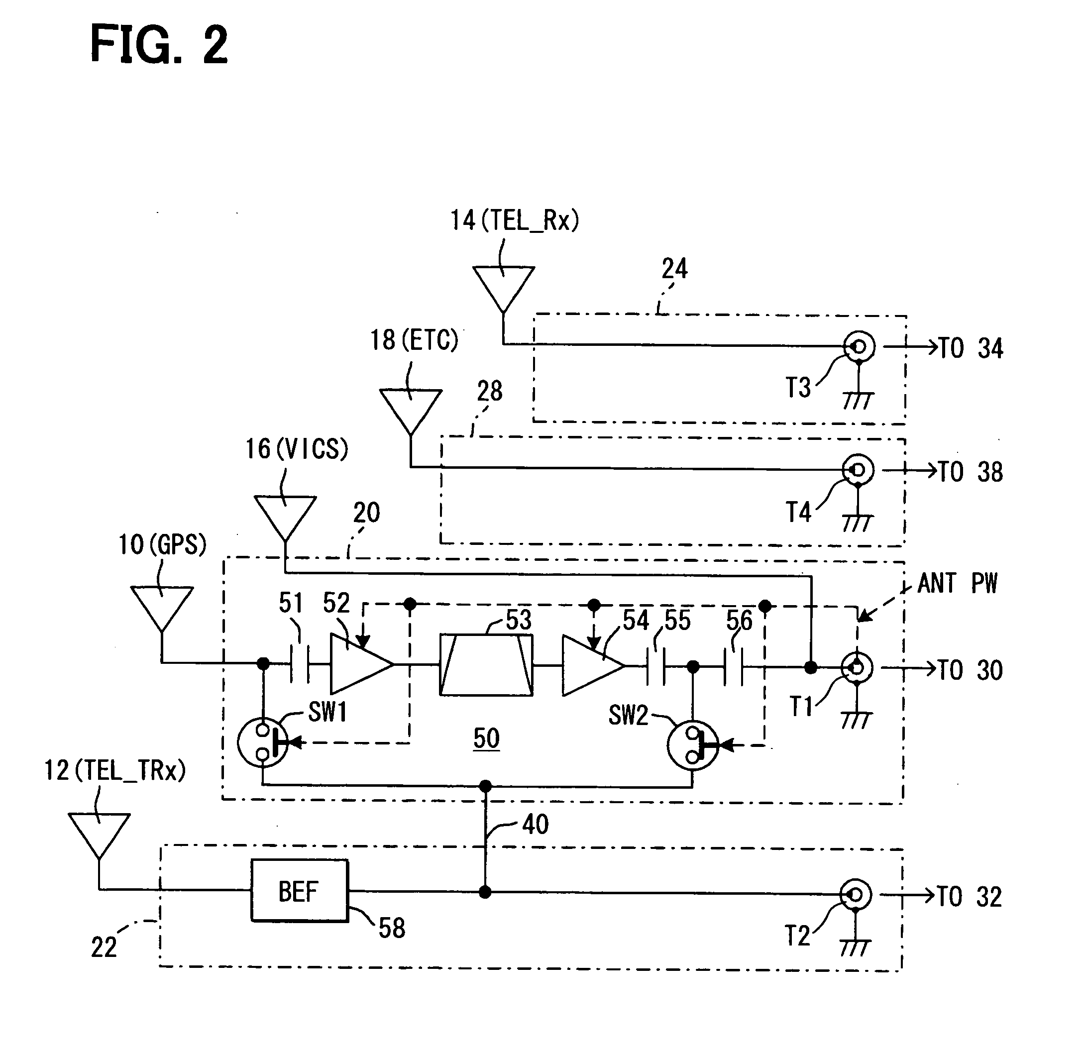
[0030]The embodiment of the present invention is described with reference to the drawing. FIG. 1 is a perspective view showing a composition of an antenna device 2 for use in the vehicle in the present embodiment, and FIG. 2 is a block diagram of a circuit configuration of the antenna device 2.

[0031]The antenna device 2 for the vehicle in the present embodiment is an integrated antenna composed by the assembly of a global positioning system (GPS) antenna element 10, TEL antenna elements 12 and 14, a vehicle information and communication system (abbreviated to “VICS”: the system is implemented and in use in Japan) antenna element 16, and an ETC antenna element 18 disposed on a ground board 4 having conductivity, and is stored in a package for installation in a position in a compartment of the vehicle as shown in FIG. 1.

[0032]Here, the GPS antenna element 10 is used to receive the electric wave for GPS transmitted by the space satellite, and is assembled on an amplification circuit bo...


PUM


Abstract

A GPS signal from a GPS antenna is provided not only for a navigation apparatus through an amplifier but also for a data communication module (DCM) through a TEL antenna for establishing communication with a station for data exchange, by devising high frequency switches that is controlled by an ON/OFF of an antenna power supply on both of an input side and an output side of the amplifier. When the amplifier is in operation, one of the switches is turned on for distributing the GPS signal to a TEL antenna side. When the amplifier is not in operation, the other switch is turned on for transmitting the GPS signal from the GPS antenna to the TEL antenna side. In this manner, the GPS signal is provided for both of the navigation apparatus and the data communication module without deteriorating signal quality from the GPS antenna.

Description

CROSS REFERENCE TO RELATED APPLICATION[0001]The present application is based on and claims the benefit of priority of Japanese Patent Application No. 2008-59634, filed on Mar. 10, 2008, the disclosure of which is incorporated herein by reference.FIELD OF THE INVENTION[0002]The present disclosure generally relates to a GPS antenna device for use in a vehicle.BACKGROUND INFORMATION[0003]Conventionally, an automotive vehicle having a navigation apparatus is equipped with an antenna device for receiving a GPS radio wave and for inputting a received GPS signal to the navigation apparatus (i.e., a GPS receiver in the navigation apparatus) through a wiring such as a co-axial cable.[0004]The antenna device has, in addition to a GPS antenna element for receiving the GPS radio wave, an amplifier for amplifying the GPS signal in the GPS radio wave to a certain level (see Japanese patent document JP-A-2008-5468, paragraph [0003], for example).[0005]When the antenna device is used in the vehicle...

Claims


Application Information

Patent Timeline
Patent Type & Authority Applications(United States)
IPC IPC(8): G01S1/00
CPCH01Q23/00H01Q1/3233G01S19/36
Inventor KOIDE, SHIROU
Owner DENSO CORP
Why Eureka
Try Eureka