Downlink Power Control Method and Apparatus in the Distributed Antenna System

a power control and antenna system technology, applied in the direction of wireless communication, power management, sustainable buildings, etc., can solve the problems of increasing the ue's power consumption, reducing the ue's standby time, and increasing the call loss of the u

Inactive Publication Date: 2008-05-01
UTSTARCOM TELECOM CO LTD
View PDF13 Cites 18 Cited by
  • Summary
  • Abstract
  • Description
  • Claims
  • Application Information

AI Technical Summary

Benefits of technology

[0012]According to one aspect of the present invention, there is provided an apparatus for controlling downlink power of the complex cell in the centralized base station system based on remote radio frequency units, said base station system having a plurality of radio frequency unit and a RAKE receiver connected to said plurality of radio frequency units, the apparatus comprising: signal quality measuring means connected to the RAKE receiver, for measuring signal quality of an uplink channel between each radio frequency unit and the same user equipment; average signal quality calculating means for calculating average signal quality of each uplink channel according to the measured signal quality; and power control means for adjusting transmission power of the downlink channel corresponding to the uplink channel according to said average signal quality, so that the transmission power of the downlink channel corresponding to the uplink channel with a lower average signal quality is relatively lower.
[0013]According to another aspect of the present invention, there is provided a method of controlling downlink power of the complex cell in the centralized base station system based on remote radio frequency units, said base station system having a plurality of radio frequency unit and a RAKE receiver connected to said plurality of radio frequency units, the method comprising: measuring signal quality of an uplink channel between each radio frequency unit and the same user equipment according to the received signal measurement by the RAKE receiver; calculating average signal quality of each uplink channel according to the measured signal quality; and adjusting transmission power of the downlink channel corresponding to the uplink channel according to said average signal quality, so that the transmission power of the downlink channel corresponding to the uplink channel with a lower average signal quality is relatively lower.

Problems solved by technology

The higher UE switching frequency will result in many potential problems: the call loss of the UE increases; the frequent radio measurement due to the switching increases the UE's power consumption, thereby reducing the UE's stand-by time; the excessive switching needs additional wireless resources, thus counteracting the increased system capacity by using micro cells.
On the other hand, when the coverage area of the centralized base station system based on remote radio frequency units is lager, i.e., the number of micro cells under control is very large, the probability that its entire region reaches the peak capacity considerably drops, and therefore many cells do not exhibit high rate of capacity utilization, thus not actually obtaining the benefit of increased potential system capacity by using micro cells.
For the remote radio frequency unit farther from the UE, its transmitted signal contributes very small to the UE's downlink receiving signal power, and therefore is unnecessary.
On the other hand, the signal transmitted to the UE by the remote radio frequency unit farther from the UE may cause the interference by its downlink on other UEs, because the distributed transmission structure of the downlink signals actually generate a man-made multipath effect, thus reducing the orthogonality of the downlinks and deteriorating the performance of the downlinks

Method used


Image

  • Downlink Power Control Method and Apparatus in the Distributed Antenna System
  • Downlink Power Control Method and Apparatus in the Distributed Antenna System
  • Downlink Power Control Method and Apparatus in the Distributed Antenna System

Examples


Embodiment Construction

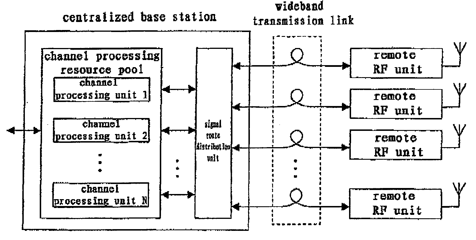
[0028]An embodiment of downlink power control device according to the present invention will be described by referring to FIGS. 4 and 6. FIG. 4 and 6 show a spreading reception device, a downlink power control device and a merging unit 20. For convenience of explanation, FIG. 4 only presents the spreading reception device corresponding to one UE. As shown in FIG. 4, the downlink power control device comprises a signal quality measuring unit 12, an average signal quality calculating unit 13 and a power control unit, wherein the power control unit comprises a selecting unit 14. As shown in the figure, the uplink reception signal from each remote radio frequency unit 11 of the complex cell is delivered to the centralized base station via a wideband transmission link for baseband processing. For the uplink, the spreading reception device of the complex cell is a receiving diversity RAKE receiver 10, where correlation reception, multipath searching and tracking processing are respectivel...


PUM


Abstract

The application discloses an apparatus for controlling downlink power of the complex cell in the centralized base station system based on remote radio frequency units, said base station system having a plurality of radio frequency unit and a RAKE receiver connected to said plurality of radio frequency units, the apparatus comprising: signal quality measuring means connected to the RAKE receiver, for measuring signal quality of an uplink channel between each radio frequency unit and the same user equipment; average signal quality calculating means for calculating average signal quality of each uplink channel according to the measured signal quality; and power control means for adjusting transmission power of the downlink channel corresponding to the uplink channel according to said average signal quality, so that the transmission power of the downlink channel corresponding to the uplink channel with a lower average signal quality is relatively lower.

Description

TECHNICAL FIELD[0001]The present invention relate to the technical field of distributed base stations in a mobile communication system, and in particular to the downlink power control method and apparatus when using the complex cell technique in a centralized base station system based on remote radio frequency units.BACKGROUND TECHNOLOGY[0002]As shown in FIG. 1a, a base station (BTS) performs transmission, reception and processing of wireless signals, and a conventional BTS is mainly composed by a baseband processing subsystem, a radio frequency (RF) subsystem and antennas, and one BTS may cover different cells through a plurality of antennas; And as shown in FIG. 1b, each BTS connects to the base station controller (BSC) or wireless networks controller (RNC) respectively through a certain interface, thereby constituting a wireless access network (RAN).[0003]FIG. 2 present another kind of distributed base station, i.e., using the system architecture of a centralized base station bas...

Claims


Application Information

Patent Timeline
Patent Type & Authority Applications(United States)
IPC IPC(8): H04B7/00H04Q7/20H04B7/005H04W52/14H04W52/40
CPCH04W52/143Y02B60/50H04W52/40
Inventor LIU, SHENG
Owner UTSTARCOM TELECOM CO LTD
Why Eureka
Try Eureka