
Method and system for enabling multi-channel direct link connection in a communication network, related network and computer program product

Active Publication Date: 2009-12-17
STMICROELECTRONICS SRL
View PDF15 Cites 68 Cited by
  • Summary
  • Abstract
  • Description
  • Claims
  • Application Information

AI Technical Summary

Benefits of technology

[0035]A preferred embodiment of the arrangement described herein is thus an architecture for WLAN cards that allows setting-up multiple, simultaneous 802.11 connections by using one WLAN card only. In such a preferred embodiment, the connections share the same data link and physical layers and the driver of the WLAN card that decides if and when to switch from a connection to the others. This makes it possible to implement networks where STAs can participate to both an infrastructure and ad-hoc network using different physical channels. In this way the STAs preserve all the advantages of an infrastructure connection (security, connection to external network) and at the same time maximize performance using different channels to transmit traffic to another node in the same cell (for example a multimedia streaming session). In such a preferred embodiment, the sender in the direct link connection autonomously selects the frequency channel to use; this is proposed through the negotiation protocol to the receiver that can eventually either reject the connection or propose a different channel, and the intervals where a STA communicates using the IM or the DLM alternate in a scheduled way while the station is always associated in the BSS.
[0040]introduces an exchange data protocol that reduces contention in the direct link communication.
[0045]the use of multiple channels allows legacy BSS and Direct Link traffic flows to be sent simultaneously;

Problems solved by technology

On the other hand, this causes a waste of possibly more than one half in the available bandwidth with respect to the case the same traffic DF were sent in ad-hoc mode.
This implies that the AP must be modified to deal with this protocol (which means that this is not IEEE 802.11 compliant).
Moreover, the problem of synchronization between stations operating in ad-hoc mode is not specifically addressed.
This prior arrangement uses the same channel for ad-hoc and infrastructure connections: this means that the traffic on the two networks is not isolated, which causes an increase in the channel contention.

Method used


Image

  • Method and system for enabling multi-channel direct link connection in a communication network, related network and computer program product
  • Method and system for enabling multi-channel direct link connection in a communication network, related network and computer program product
  • Method and system for enabling multi-channel direct link connection in a communication network, related network and computer program product

Examples


Embodiment Construction

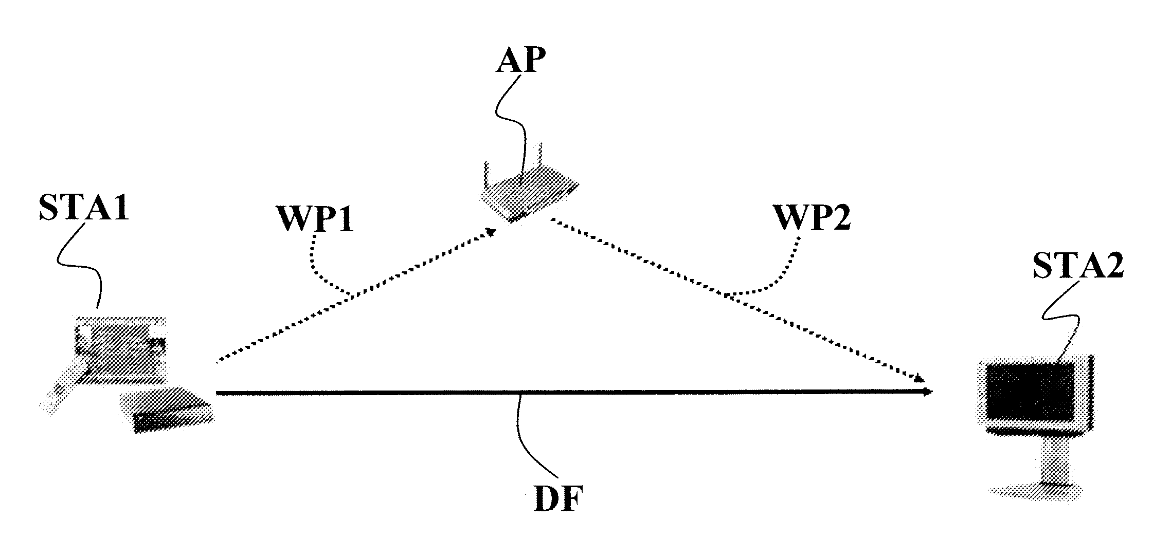
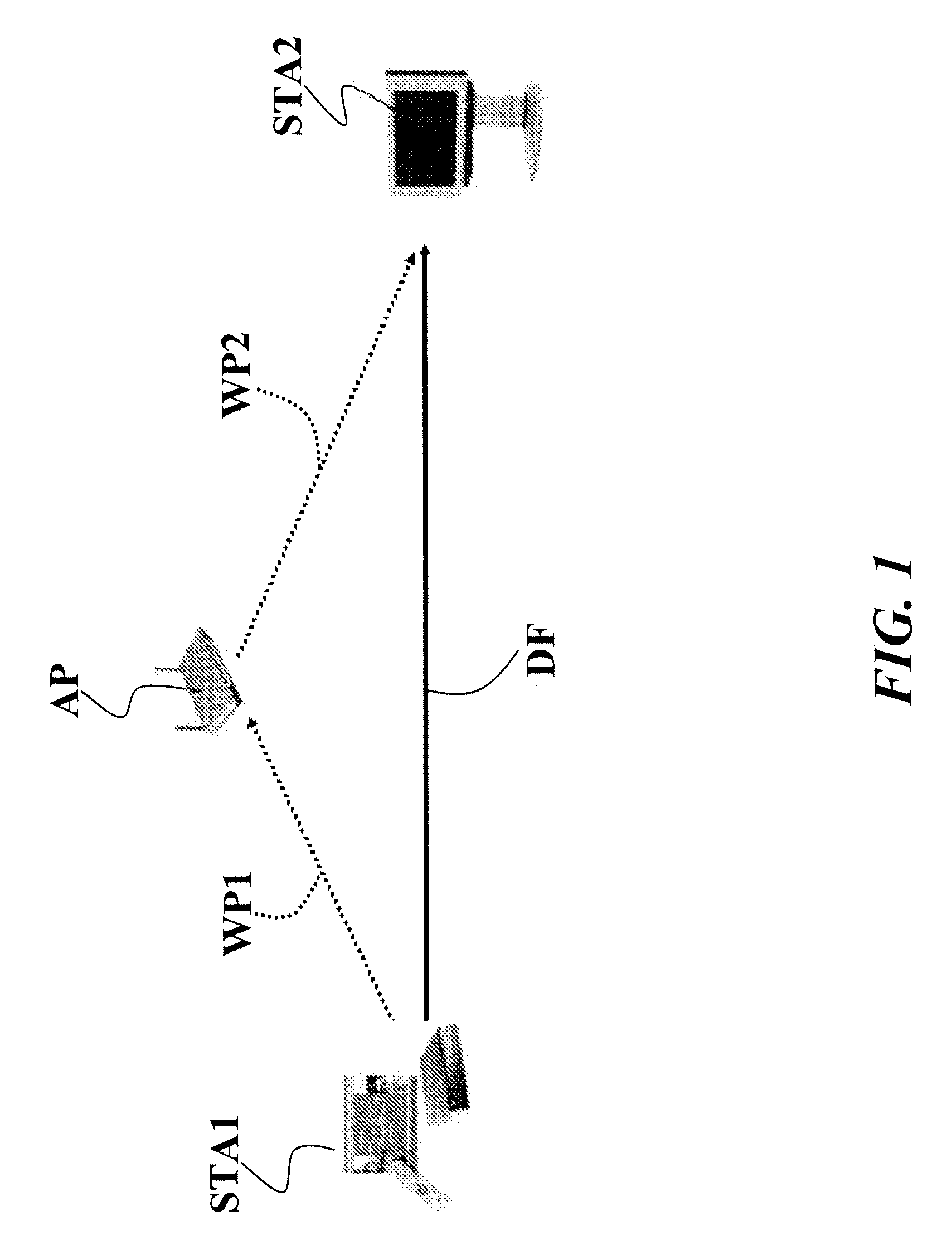
[0058]As indicated, in a general WLAN scenario, a wireless STA such as STA1 and STA 2 shown in FIG. 1, can operate in one of two possible transmission modes:[0059]Infrastructure Mode (IM): STA1 and STA2 communicate through the AP as in a standard 802.11 BSS; this mode is obviously mandatory if either of STA1 or STA2 is the AP; or

[0060]Direct link mode (DLM): two stations (STA1 and STA2) belonging to the same BSS directly communicate using an ad-hoc connection over an assigned channel.

[0061]The two modes introduce two alternative paths to connect the two BSS stations, namely a two hop path (STA1->AP->STA2) for IM and a single hop path (STA1->STA2) for the DLM.

[0062]The basic idea underlying the arrangement described herein can be briefly explained as follows.

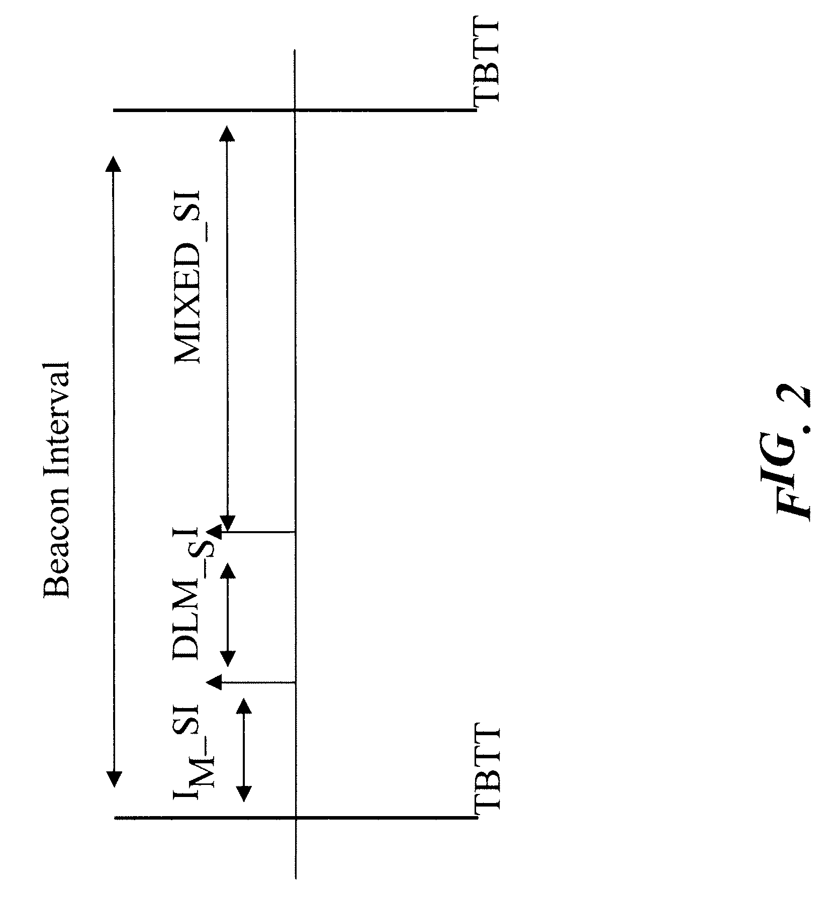
[0063]The main time frame entity of a wireless STA is the beacon interval, shown in FIG. 2. Each beacon interval starts with a beacon frame. This is a management frame that the AP sends periodically, at each Target Beacon Transmi...


PUM


Abstract

A wireless communication network includes an access point and a plurality of stations. The access point sends towards the stations periodic information arranged in time frames or beacon intervals. The stations in the network are configured to in a first mode through the access point, and in a second mode directly with each other. The time frames are partitioned into a first time interval wherein the stations communicate in the first mode over a first channel; a second time interval wherein the stations communicate in the second mode over a second channel, and a third time interval wherein the stations communicate in either of the first or the second mode.

Description

FIELD OF THE INVENTION[0001]The present invention relates to communication networks and was developed with specific attention paid to its possible application to wireless Local Area Networks (wireless LANs or WLANs).DESCRIPTION OF THE RELATED ART[0002]The IEEE 802.11 wireless LAN standard (IEEE Wireless LAN Edition. IEEE Std 802.11™-1999 Reissue 2003) stipulates that wireless stations can communicate with each other using one of two modes: the infrastructure mode and the ad-hoc mode.[0003]In the infrastructure mode, sometimes referred to as Access Point (AP) mode, a wireless station, STA, is associated with an 802.11 Access Point and can send / receive data to / from the AP only. The set of stations associated to an AP is referred as Basic Service Set, BSS. An Intra-cell communication (i.e. a communication where the source and destination are in the same BSS) that is relayed by the AP will be referred to as “legacy BSS connection”. The AP provides connectivity to external networks, as w...

Claims


Application Information

Patent Timeline
IPC IPC(8): H04W84/12
CPCH04W72/04H04W76/021H04W84/12H04W76/043H04W76/025H04W76/23H04W76/15H04W76/11
Inventor CONVERTINO, GABRIELLAPARATA, CARLOSCARPA, VINCENZO
Owner STMICROELECTRONICS SRL
Learn More