Portable electronic device with broadcast antenna

a portable wireless communication and electronic device technology, applied in the direction of substation equipment, antenna details, antennas, etc., can solve the problems of limited shape of portable wireless communication electronic devices, easy damage of antennas, etc., and achieve the effect of improving the quality of received broadcasting signals, and prolonging the path length

Inactive Publication Date: 2009-12-17
ARIMA COMM CORP LTD
View PDF2 Cites 44 Cited by
  • Summary
  • Abstract
  • Description
  • Claims
  • Application Information

AI Technical Summary

Benefits of technology

[0007]An object of the present invention is to provide a portable electronic device with broadcast antenna which is divided into two parts, a main body and a separable cover, wherein the broadcast antenna is disposed on the inner surface of the cover other than a battery area, so that the broadcast antenna with longer path length can be accommodated in the housing of the portable electronic device. Therefore, the portable electronic device with broadcast antenna according to the present invention can have a dedicated broadcast antenna with qualified return loss, bandwidth and performance, and thus, the quality of received broadcasting signals becomes more stable and better.

Problems solved by technology

In the conventional portable wireless communication electronic device in which earphone is served as FM antenna for reducing the volume, since earphone is not a dedicated antenna, the return loss, bandwidth and performance thereof are not qualified, and further, the different earphone choices by users also might influence the quality of the received FM wireless broadcasting signals.
As to the portable wireless communication electronic device with telescopic antenna, since the antenna thereof has to be expanded to a specific length, such as the longest length, for achieving the qualified return loss, bandwidth and performance, the antenna might be easily damaged owing to the frequent expansion and contraction operations, and further, the shape of the portable wireless communication electronic device might also be limited thereby.

Method used


Image

  • Portable electronic device with broadcast antenna
  • Portable electronic device with broadcast antenna
  • Portable electronic device with broadcast antenna

Examples


Embodiment Construction

[0016]The present invention will now be described more specifically with reference to the following embodiments. It is to be noted that the following descriptions of preferred embodiments of this invention are presented herein for purpose of illustration and description only. It is not intended to be exhaustive or to be limited to the precise form disclosed.

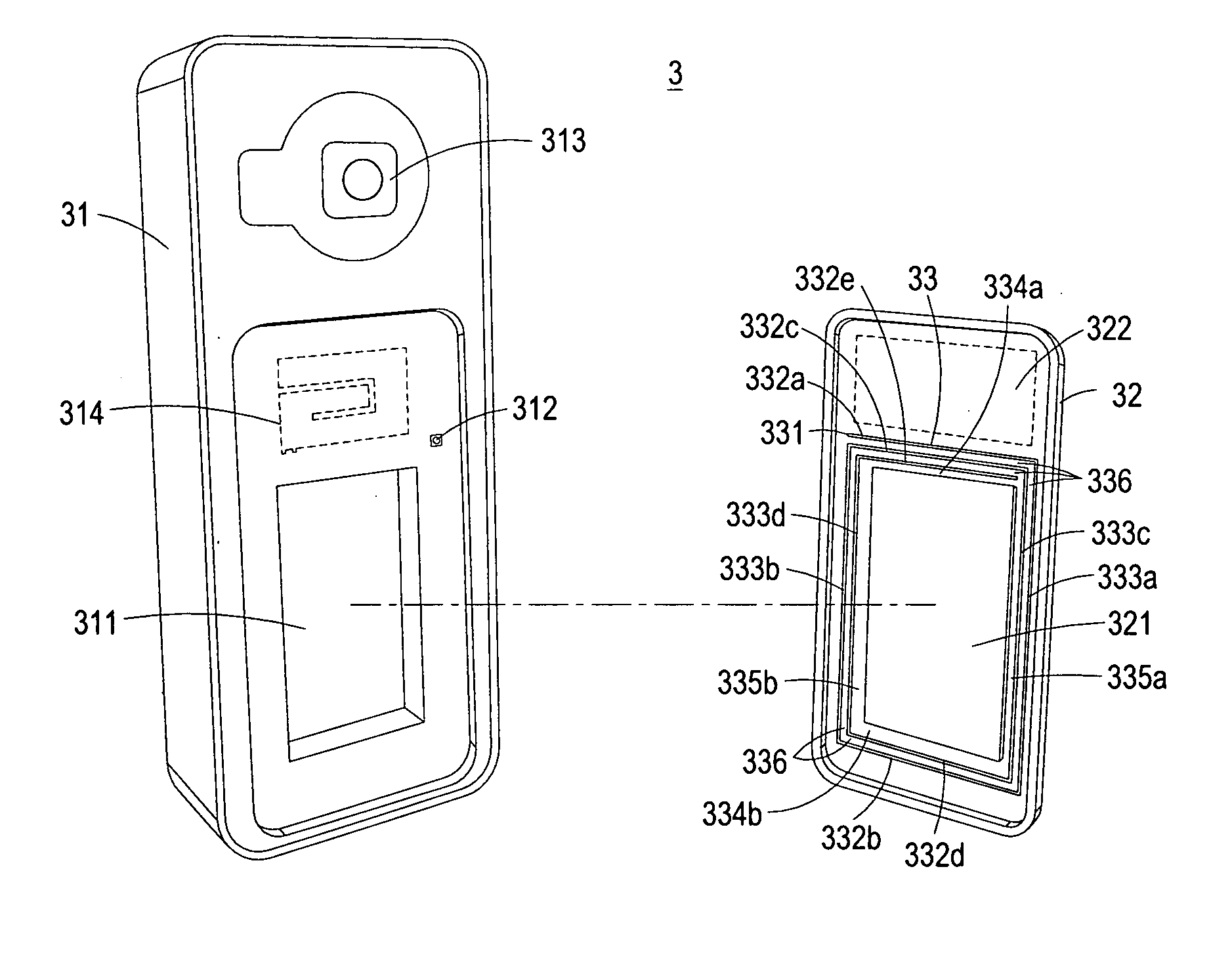
[0017]Referring to FIG. 3, a schematic view of a portable electronic device with broadcast antenna in a preferred embodiment of the present invention is shown. As shown, the portable electronic device 3 with broadcast antenna of the present invention includes a main body 31, a cover 32 and a broadcast antenna 33. The main body 31 has a battery accommodating space 311 for disposing battery (not shown). The cover 32, such as battery cover, has a battery area 321 corresponding to the battery accommodating space 311, and the shape and size of the cover 32 are adapted to cover the battery accommodating space 311, wherein the cover 32 ...


PUM


Abstract

The present invention is related to a portable electronic device with broadcast antenna at least including a main body having a battery accommodating space; a cover having a battery area corresponding to the battery accommodating space of the main body, wherein the shape and size of the cover are adapted to cover the battery accommodating space and the cover is separablely assembled with the corresponding outer edge of the battery accommodating space of the main body; and a broadcast antenna, disposed on the inner surface of the cover other than the battery area for unidirectionally receiving broadcasting signals in a first frequency band.

Description

FIELD OF THE INVENTION[0001]The present invention is related to a portable electronic device, and more particularly to a portable electronic device with broadcast antenna.BACKGROUND OF THE INVENTION[0002]In recent years, the development of the wireless communication industry is vigorous. Especially, some portable wireless communication electronic devices, for example, cell phones or PDAs, have become indispensable commodities for people. An antenna generally plays an important role for transmitting and receiving wireless signals in a portable wireless communication electronic device. Therefore, the operating characteristics of the antenna have a direct impact on the transmission and receiving quality for the portable wireless communication electronic device.[0003]Nowadays, owing to the miniaturization of the portable wireless communication electronic device and the improvement of portability thereof, the antenna in the portable wireless communication electronic device, except for ha...

Claims


Application Information

Patent Timeline
Patent Type & Authority Applications(United States)
IPC IPC(8): H04B1/38H04W88/02H04M1/00
CPCH01Q1/243H01Q1/362H04M1/0262H01Q9/0421H01Q7/00
Inventor PENG, HUANG-TSELAI, KUO-JENHSIAO, E-DEN
Owner ARIMA COMM CORP LTD
Why Eureka
Try Eureka