Guide Sheath Dilator And Method Of Using The Same

a technology of dilators and guides, which is applied in the field of selective guide sheath dilators, to achieve the effect of reducing the trauma caused by access and facilitating movement through the vasculatur

Inactive Publication Date: 2009-12-17
TERUMO MEDICAL CORP
View PDF24 Cites 52 Cited by
  • Summary
  • Abstract
  • Description
  • Claims
  • Application Information

AI Technical Summary

Benefits of technology

[0010]The stiffness sections are fused together thereby creating varying stiffness and / or flexibility in the dilator. The dilator further includes a lumen that traverses an interior of the shaft from the proximal end to the distal end as well as a hub that is located on the proximal end of the shaft.
[0013]The dilator may also contain one or more radiopaque markers in the distal area to improve visibility under fluoroscopy and possibly be used for measurement approximations. The dilator may also have a shaped distal end to allow easier vessel selection. Further, the distal end may have apertures located near the tip of the dilator so as to deliver contrast media to a work-destination area.
[0021]Trauma caused by the access is reduced due to the varying stiffnesses of the dilator because the stiffnesses allow the dilator to move easier through the vasculature. When the dilator is removed from the sheath, the sheath retains a uniform rigidity which allows for placement of medical equipment at the distal end of the sheath.

Problems solved by technology

The disadvantage of the above system and method is that the dilator typically used as a mechanism for guiding the sheath into a blood vessel is made from a uniform material designed primarily for the initial access.

Method used


Image

  • Guide Sheath Dilator And Method Of Using The Same
  • Guide Sheath Dilator And Method Of Using The Same
  • Guide Sheath Dilator And Method Of Using The Same

Examples


first embodiment

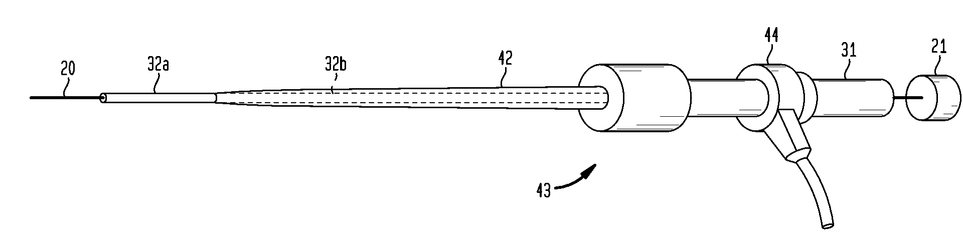
[0034]In addition, as can be seen from FIG. 1, the dilator device 30 of the present invention offers multiple stiffness sections 32a-b. That is, the dilator device 30 includes a shaft 32 that has a distal end 33, a proximal end 34 and two stiffness sections 32a-b. These stiffness sections 32a-b become less rigid as they approach the distal end 33. In other words, the shaft is the softest at the distal end (approximately 30 shore D to 70 shore D) and transitions to the stiffest section at the proximal end (approximately 50 shore D to 80 shore D). The varying stiffness sections 32a-b allow the dilator device 30 to slightly bend around twisted and bent vasculature, so as the dilator 32 is advanced and the stiffness is changed, the bent vasculature is straightened. The varying stiffness sections also provide for greater pushability when advancing through the vasculature.

[0035]The dilator 32 may also taper along the length the dilator 33. That is, the dilator may taper along the full len...

second embodiment

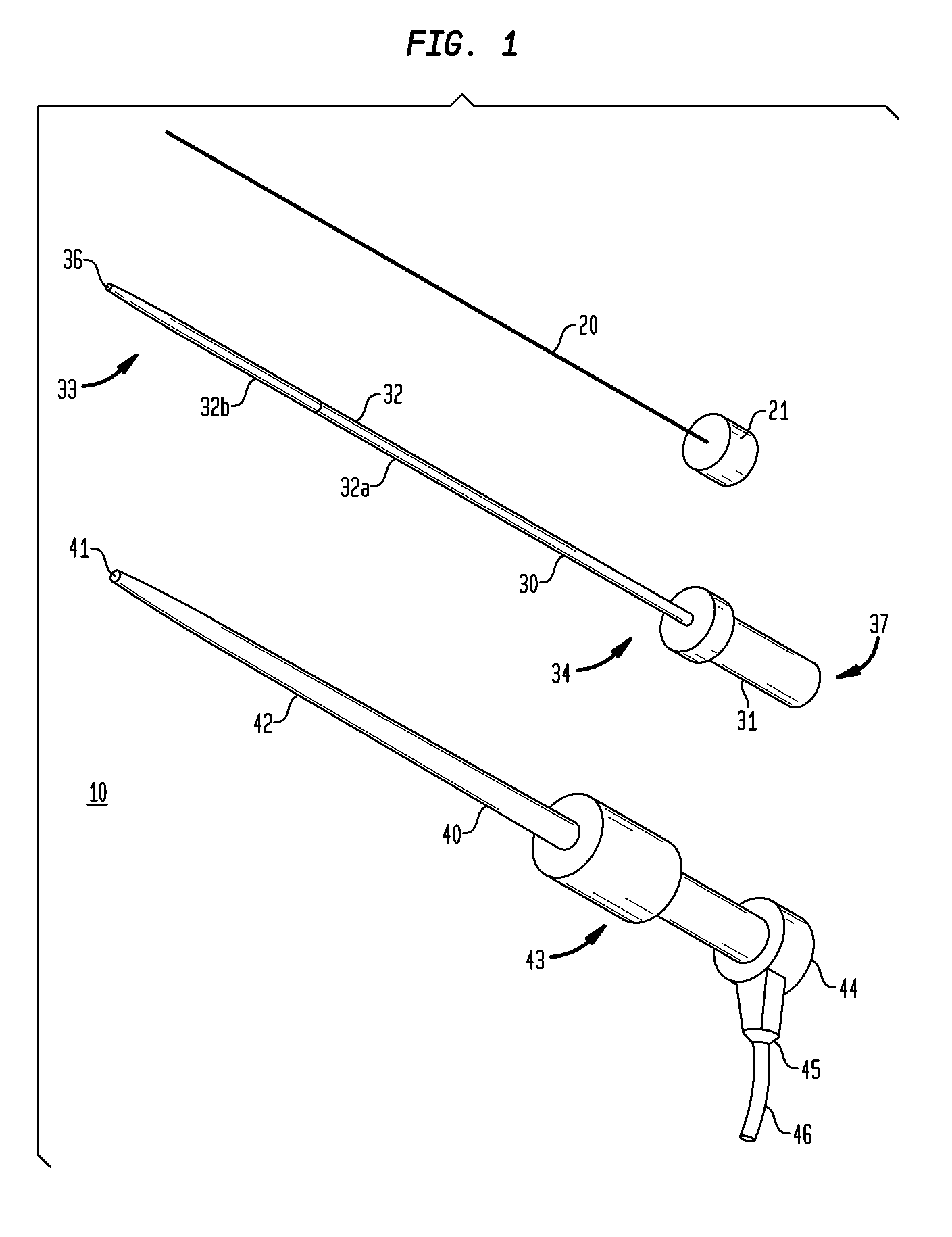
[0042]In a second embodiment, as shown in FIG. 2, the shaft 51 may have three stiffness sections 51a-c. The first stiffness section 51a may be approximately 25-90 cm in length with a durometer of approximately 50 shore D to 80 shore D, the second stiffness section 51b may be approximately 1-70 cm in length with a durometer of approximately 30 shore D to 70 shore D and the third stiffness section 51c may be approximately 1-70 cm in length with a durometer of approximately 40 shore A to 40 shore D.

[0043]The material blends of these stiffness sections also vary significantly depending on application and length of the dilator. The stiffness sections 51a-c can also be made from a blend of between 0-95% PP impact copolymer and between 5-100% high performance elastomer (TPV). In a preferred embodiment, the first stiffness section 51a may be made from an approximate blend of 50% high performance elastomer (TPV) and 50% PP impact copolymer containing approximately 30% Bi2SO4, the second stif...

third embodiment

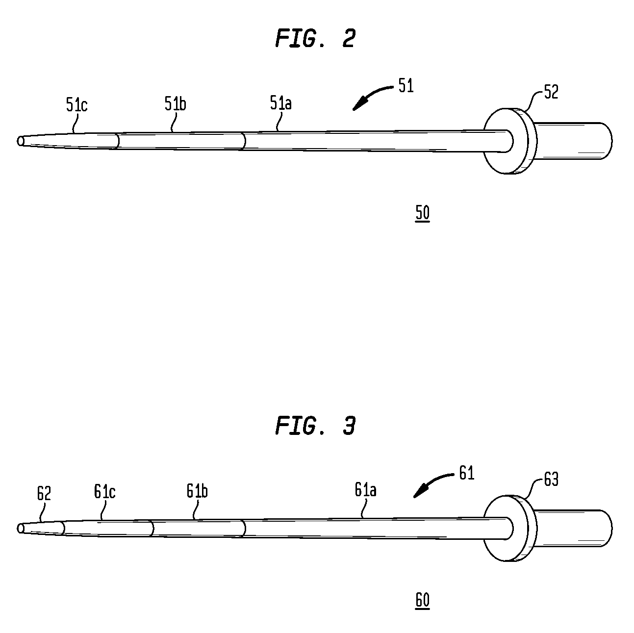
[0044]In a third embodiment, as shown in FIG. 3, a tip 62 can be connected to the distal end of the shaft 61. The tip would be the softest and least rigid section of the shaft 61 resulting in an atraumatic tip 62. In this embodiment, the tip is attached to a dilator 60 having three stiffness sections 61a-c. But the tip may be used in conjunction with a shaft having any number of stiffness sections including a shaft that has a substantially even gradient of stiffness.

[0045]The dilators 30, 50 and 60 are all used in conjunction with the sheath device 40. These dilators 30, 50 and 60 are coaxially disposed within a lumen 41 of the sheath device 40. The sheath 40 is approximately 90 cm long when used with a femoral access point but longer (approximately 120 cm) and shorter (approximately 30 cm) sheaths and dilators may be used when accessing a vessel.

[0046]The sheath device 40 includes an elongated tubular sheath 42, a hub 43 and a valve 44. The sheath 42 can be secured to the hub 43 by...


PUM


Abstract

The present invention relates to a dilator. The dilator includes a shaft, a lumen and a hub. The shaft has at least two stiffness sections with the stiffness sections becoming less rigid as they approach a distal end of the shaft. The varying stiffness sections allow the dilator to track along the guidewire through torturous vasculature so as the dilator is advanced and the stiffness is changed, the stiffer sheath can advance smoothly through a blood vessel. The dilator may also taper at the distal tip to stretch the initial skin puncture hole larger to accommodate the dilator shaft and ease the sheath tip insertion through to the vasculature. Or the shaft may taper from where it extends beyond the sheath distal tip to the distal end so that it can reach further distal in the vasculature. The dilator may also include an atraumatic tip for easier advancement of the dilator. The dilator distal end may also include one or more radiopaque markers and a shaped distal end.

Description

BACKGROUND OF THE INVENTION[0001]1. Field of the Invention[0002]The present invention relates to a dilator. Specifically, the present invention relates to a selective guide sheath dilator with multiple stiffness sections.[0003]2. Background of the Invention[0004]In today's medical field, many medical procedures require entry into a patient's blood vessel for purposes of accessing a desired site, e.g., angioplasty and stenting. In order to gain access to the desired site, a sheath is usually advanced through the blood vessel. Once in place within the patient's vessel, various types of medical instrumentation can be fed through the sheath and positioned at the desired site so that the procedure may be performed.[0005]To initially gain access to a particular site within a patient, a needle is used to puncture the patient's skin and gain entry to a desired blood vessel. A guide wire is then inserted into a lumen in the needle and is fed into the blood vessel. The needle is then removed,...

Claims


Application Information

Patent Timeline
Patent Type & Authority Applications(United States)
IPC IPC(8): A61M29/00
CPCA61M25/007A61M25/0606A61M2025/0687A61M29/00A61M25/0662
Inventor TRASK, LINDAFERGUSON, FRANKANDERSON, SUSAN
Owner TERUMO MEDICAL CORP
Why Eureka
Try Eureka