Stall prediction apparatus, prediction method thereof, and engine control system

a technology of stall prediction and prediction method, which is applied in the direction of machines/engines, process and machine control, instruments, etc., can solve the problems of adiabatic efficiency decline, failure to diagnose faults, and pressure ratio drop, so as to improve the accuracy of fault diagnosis and high reliability

Active Publication Date: 2009-12-17
IHI CORP +1
View PDF13 Cites 26 Cited by
  • Summary
  • Abstract
  • Description
  • Claims
  • Application Information

AI Technical Summary

Benefits of technology

[0022]In accordance with the present invention, it is possible to obtain a stall risk index which is highly accurate (supersensitive) and stable which is necessary for an active stall control by eliminating a time-wise fluctuation in the stall risk index and an influence of a circumferential nonuniformity. By obtaining the stall risk index which is highly accurate (supersensitive) and stable, it is possible to improve the accuracy of fault diagnoses of the pressure sensors, whereby it is possible to realize a stable engine control system provided with high reliability necessary for the active stall control.

Problems solved by technology

In an axial compressor which is used for a gas turbine engine, a jet engine, or the like, when a stall occurs, failures occur such as a decrease in a pressure ratio, a decrease in an adiabatic efficiency, a decrease in an inflow rate, an adverse flow of an air, or the like.
Accordingly, a conventional axial compressor needed to operate with a sufficient margin from an originating point of the stall phenomenon, whereby it was not possible to operate it with its potential performance.

Method used


Image

  • Stall prediction apparatus, prediction method thereof, and engine control system
  • Stall prediction apparatus, prediction method thereof, and engine control system
  • Stall prediction apparatus, prediction method thereof, and engine control system

Examples


Embodiment Construction

[0058]An Embodiment of the present invention shall be described with reference to drawings.

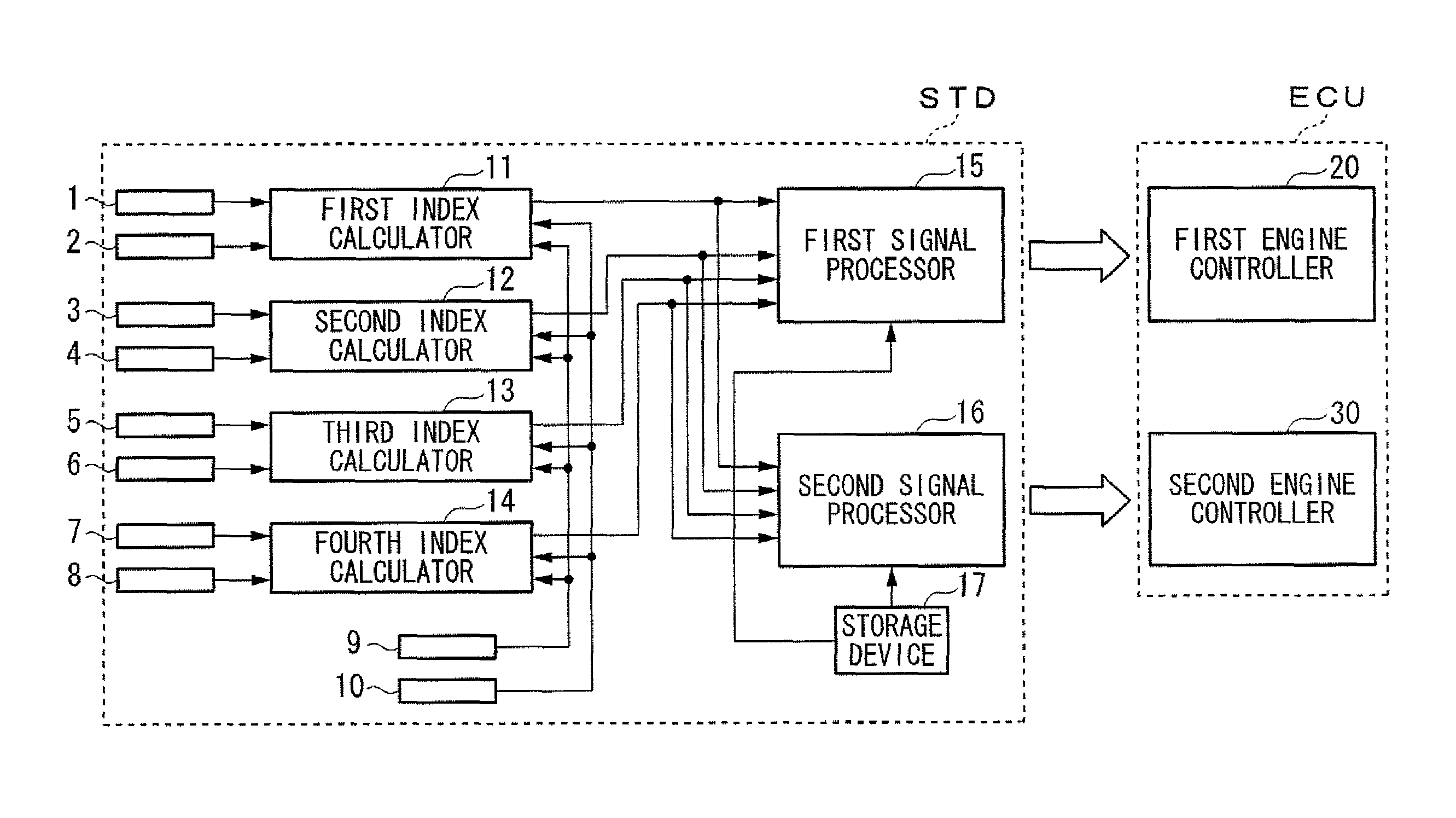
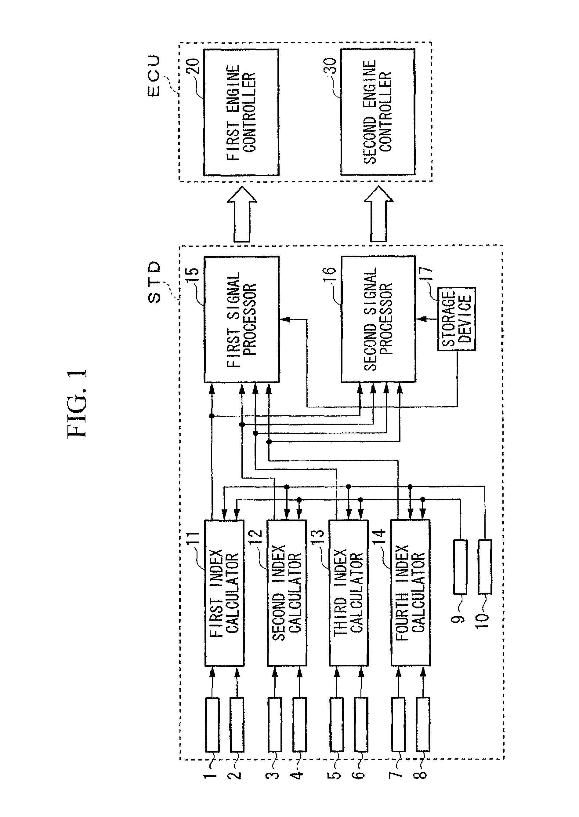
[0059]FIG. 1 is a structural block diagram of an engine control system in accordance with an embodiment of the present invention. The engine control system is a control system for a gas turbine engine provided with an axial compressor, a jet engine, or the like. The engine control system has an STD (stall prediction apparatus) for predicting a stall occurrence of the axial compressor and an ECU (engine control unit) for controlling the engine based on a stall prediction result by the stall prediction apparatus STD. Here, the engine control unit ECU has two systems of engine controller (a first engine controller 20 and a second engine controller 30).

[0060]The stall prediction apparatus STD has a first pressure sensor 1 to an eight pressure sensor 8, a first rotating speed sensor 9 and a second rotating speed sensor 10, a first index calculator 11 to a fourth index calculator 14, a first signal ...


PUM


Abstract

A stall prediction apparatus of an axial compressor provided with: a rotor provided with a plurality of rotor blades; and a cylindrical casing facing the rotor blades and provided so as to cover the outer circumference of the rotor, comprising: pressure sensors provided in equal numbers at a plurality of locations in a circumferential direction of an inner wall surface of the casing, an index calculator for calculating an index (stall risk index) for evaluating the stall risk based on time-series data detected by each of the pressure sensors, and a signal processor for predicting the stall occurrence based on the stall risk indexes obtained corresponding to said each of the pressure sensors. In accordance with the present invention, it is possible to obtain a stall risk index which is highly accurate (supersensitive) and stable necessary for the active stall control, and to realize an engine control system with high reliability.

Description

TECHNICAL FIELD[0001]The present invention relates to a stall prediction apparatus, prediction method thereof, and an engine control system.[0002]Priority is claimed on Japanese Patent Application No. 2006-140257, filed on May 19, 2006, the content of which is incorporated herein by reference.BACKGROUND ART[0003]In an axial compressor which is used for a gas turbine engine, a jet engine, or the like, when a stall occurs, failures occur such as a decrease in a pressure ratio, a decrease in an adiabatic efficiency, a decrease in an inflow rate, an adverse flow of an air, or the like. Accordingly, a conventional axial compressor needed to operate with a sufficient margin from an originating point of the stall phenomenon, whereby it was not possible to operate it with its potential performance.[0004]In order to solve these problems, an engine control (active stall control) is proposed which predicts a stall occurrence and avoids the stall from occurring by an actuation. As a stall predi...

Claims


Application Information

Patent Timeline
Patent Type & Authority Applications(United States)
IPC IPC(8): G06F19/00F02G3/00F02C9/00F04D27/00
CPCF01D17/08F02C9/16F04D27/0292F05D2270/301F05D2270/44F05D2270/708F05D2270/101G05B9/03F04D27/001
Inventor NAKAKITA, TOMOFUMITOMIYAMA, TAKASHITAKEMURA, FUMITAKA
Owner IHI CORP
Why Eureka
Try Eureka