Generation of trace data in a multi-processor system

a multi-processor system and trace data technology, applied in the field of trace data generation, can solve the problems of increasing the complexity of the system, unable to track the architecture of the processor (such as the contents of registers, values stored at particular memory locations, flags or modules within the processing system) via externally accessible pins

Active Publication Date: 2009-12-17
ARM LTD
View PDF8 Cites 26 Cited by
  • Summary
  • Abstract
  • Description
  • Claims
  • Application Information

AI Technical Summary

Benefits of technology

[0033]It will be appreciated that the configurable condition in dependence upon which the selection circuitry selects which of the plurality of processing circuits to trace could be configured in any one of a number of different ways, for example, by a test engineer. However, in one embodiment, the apparatus comprises a programming interface and the configurable condition is configurable by debugging software via the programming interface. This provides a convenient means by which control of the selective switching of the tracing circuitry, can be performed.
[0034]In one embodiment, the memory to which the plurality of processing circuits of the data processing apparatus have access comprises a coherency controller and the processing state information (in dependence upon which the selective switching is performed) is output by the coherency controller. This enables efficient tracing of activity corresponding to a given storage location in the memory system associated with the data processing apparatus. In one such embodiment the processing state information comprises an indication of which of the plurality of processors currently has write access to a given location in the memory.
[0035]It will be appreciated that the selection circuitry could be configured such that changes to the processing state information would always be likely to give rise to a switch between tracing of one of the plurality of processing circuits to another different one of the plurality of processing circuits. However, in one embodiment, the selection circuitry is configurable to suppress the selective switching of the tracing activity such that whilst the suppression is performed, the tracing activity generates a trace data stream corresponding to a given one of the plurality of processing circuits regardless of the processing state information. This provides the additional flexibility to focus tracing activity on a given one of the processing circuits of the multi-processor device rather than tracing based upon, for example, which processor is currently executing a given processing task.

Problems solved by technology

There is a requirement for data processing systems having improved performance and functionality, which typically means an increase in the complexity of the systems.
There is a general move towards more deeply-embedded processor cores, which makes it more difficult to track the architectural state of the processor (such as the contents of registers, values stored at particular memory locations or status of the buses, paths, lines, flags or modules within the processing system) via externally accessible pins.
However, tracing circuitry such as ETMs are expensive in terms of silicone area so that it becomes inefficient to supply such multi processor systems with separate sets of tracing circuitry corresponding to each of the plurality of processors of the system.
However, such static switching is inflexible since it does not allow a given processing task to be fully traced if the task under observation moves from processor to processor.
However, even in multi-processor systems having multiple ETMs, trace bandwidth constraints are likely to mean that it is still not possible to enable tracing on a plurality of ETMs substantially simultaneously.

Method used


Image

  • Generation of trace data in a multi-processor system
  • Generation of trace data in a multi-processor system
  • Generation of trace data in a multi-processor system

Examples


second embodiment

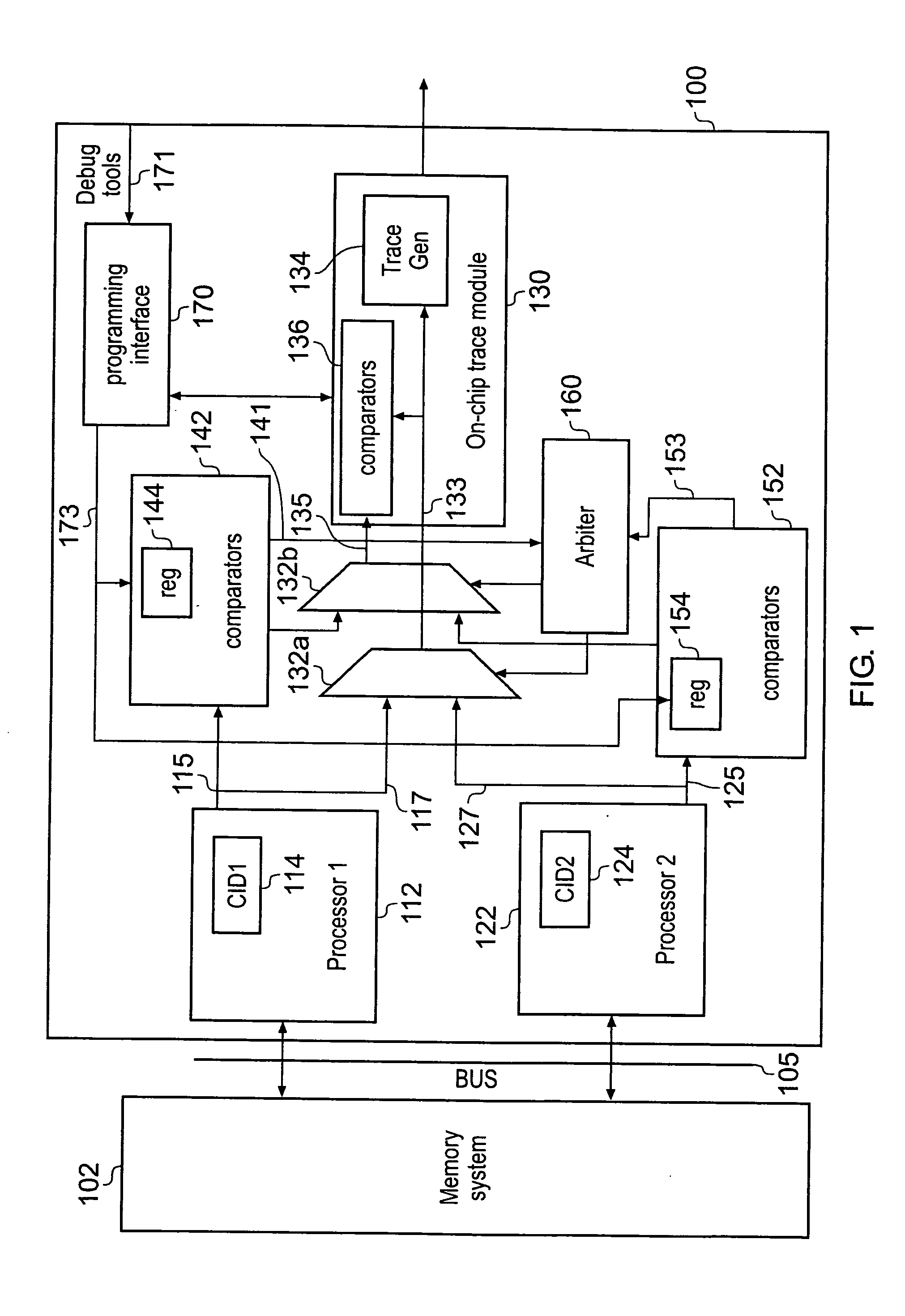
[0075]FIG. 4 schematically illustrates a symmetric multi-processor system. In this arrangement, instead of providing a single common on-chip trace module shared between the first and second processors for tracing of both data and instructions, a single common on-chip trace module is provided to perform data trace, whereas separate instruction tracing circuitry is provided for each of the two processors 112, 122. The memory system 102, first and second processors 112, 122 and their respective comparator modules 142, 152 perform the same functions as the correspondingly numbered elements of FIG. 1. Also, similarly to FIG. 1, the multiplexer 132 is controlled by the arbitration circuitry 160 to output to diagnostic data either from the first processor 112 or the second processor 122 in dependence upon whether or not there is a match between the context ID for the respective processor and the process of interest to the debug tools.

[0076]However, the arrangement of FIG. 4 has an on-chip ...

third embodiment

[0079]FIG. 5 schematically illustrates a multi-processor system which uses comparison resources integral to the individual processors to provide processing state information to the tracing circuitry. The arrangement of FIG. 5 comprises: a memory system 502; a first processor 512; a second processor 522; arbitration circuitry 560; a multiplexer 532; an on-chip trace module 530 and a program interface 570. The first processor 512 has a first breakpoint unit 514 whilst the second processor 522 has a second breakpoint unit 524. The on-chip trace module 530 of the embodiment of FIG. 5 is similar in structure and function to the on-chip trace module 130 of FIG. 1 and it traces both data and instructions. However, in the embodiment of FIG. 5, the multiplexer 532 switches between output diagnostic data from the first processor 512 to output data corresponding to the second processor 524 in dependence upon a control signal issued by the arbitration circuitry 560.

[0080]The arbitration circuit...

fourth embodiment

[0084]FIG. 6 schematically illustrates a symmetric multi-processor system. In this embodiment the processing state information used to guide selective switching between outputting diagnostic information from a first processor to a second processor is state information derived from the memory system rather than directly from the processors.

[0085]The arrangement of FIG. 6 comprises: a memory system 602 having a coherency controller 604; a first processor 612: a second processor 622; a multiplexer 632; an on-chip trace module 630; a comparator 606; arbitration circuitry 660; and a program interface 670. In this embodiment, the arbitration circuitry 660 controls the multiplexer 632 to switch between outputting diagnostic data of the first processor 612 and the second processor 622 in dependence upon processing state information derived from the coherency controller 604 of the memory system 602. Thus, in the FIG. 6 embodiment, information from the memory system 602 rather than from the p...


PUM


Abstract

A data processing apparatus is provided having a plurality of processing circuits each having access to a memory. Tracing circuitry is provided for generating a stream of trace data for generating a stream of trace data corresponding to at least one of the plurality of processing circuits. Selection circuitry is provided to enable selective switching of the tracing circuitry from generating a first trace data stream corresponding to a first one of the plurality of processing circuits generating a second different trace data stream corresponding to a different one of the plurality of processing circuits. The selective switching is performed in dependence upon processing state information associating with one or more of the plurality of processing circuits. A corresponding method and computer program product are also provided.

Description

BACKGROUND OF THE INVENTION[0001]1. Field of the Invention[0002]The present invention relates to the generation of trace data within a data processing apparatus.[0003]2. Description of the Prior Art[0004]There is a requirement for data processing systems having improved performance and functionality, which typically means an increase in the complexity of the systems. Furthermore, there is a requirement to reduce the development and testing time for these more complex data processing systems, which means that there is an increasing need for powerful yet easy-to-use diagnostic mechanisms for identifying problems associated with data processing systems and to improve the performance of those data processing systems by adjusting their design and configuration.[0005]There is a general move towards more deeply-embedded processor cores, which makes it more difficult to track the architectural state of the processor (such as the contents of registers, values stored at particular memory loca...

Claims


Application Information

Patent Timeline
Patent Type & Authority Applications(United States)
IPC IPC(8): G06F11/34
CPCG06F11/3636G06F11/348
Inventor SWAINE, ANDREW BROOKFIELDWILLIAMS, MICHAEL JOHNHART, DAVID KEVINROSE, ANDREW CHRISTOPHER
Owner ARM LTD
Why Eureka
Try Eureka