
Method of dewatering solids laden liquids utilizing a reusable filter element

Active Publication Date: 2009-12-24
CONWELL MICHAEL K
View PDF89 Cites 18 Cited by
  • Summary
  • Abstract
  • Description
  • Claims
  • Application Information

AI Technical Summary

Benefits of technology

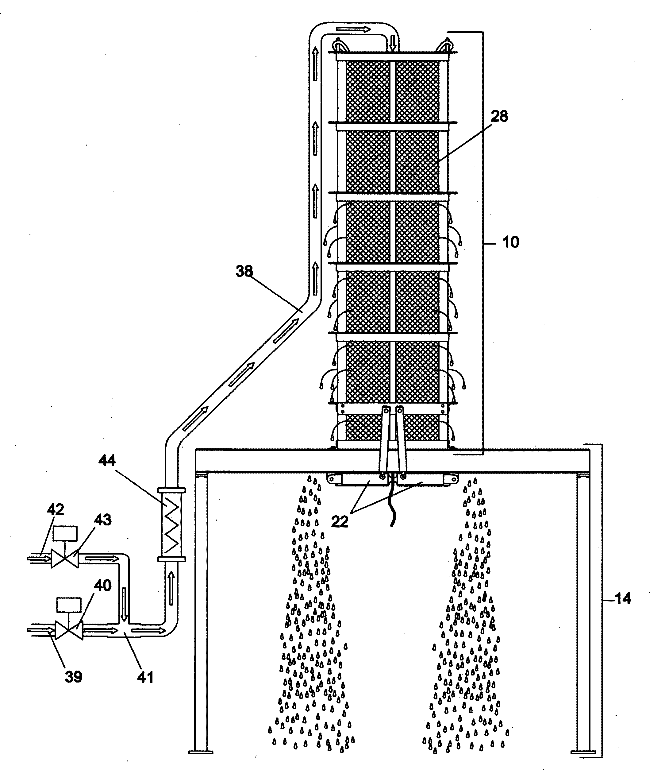
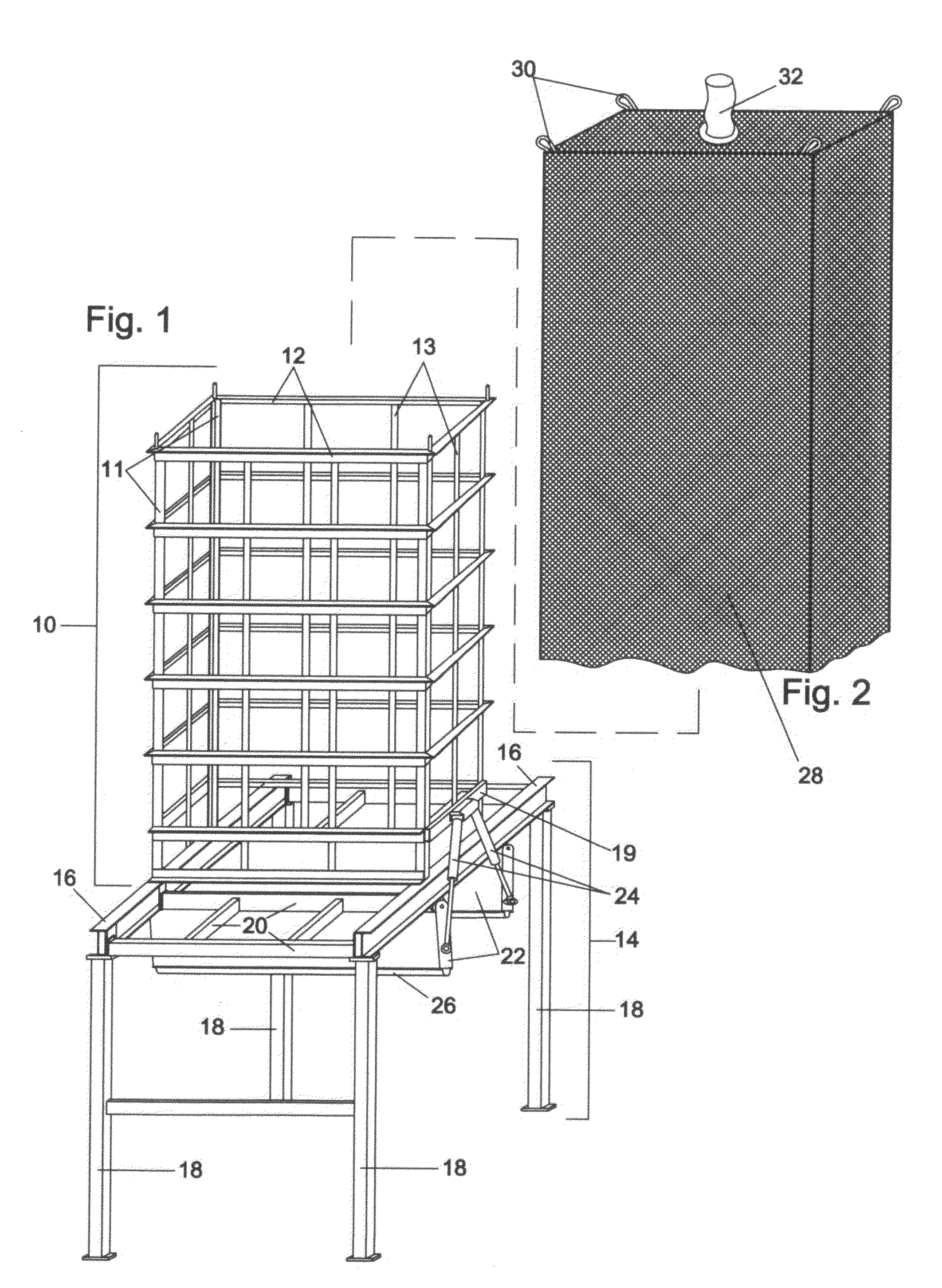
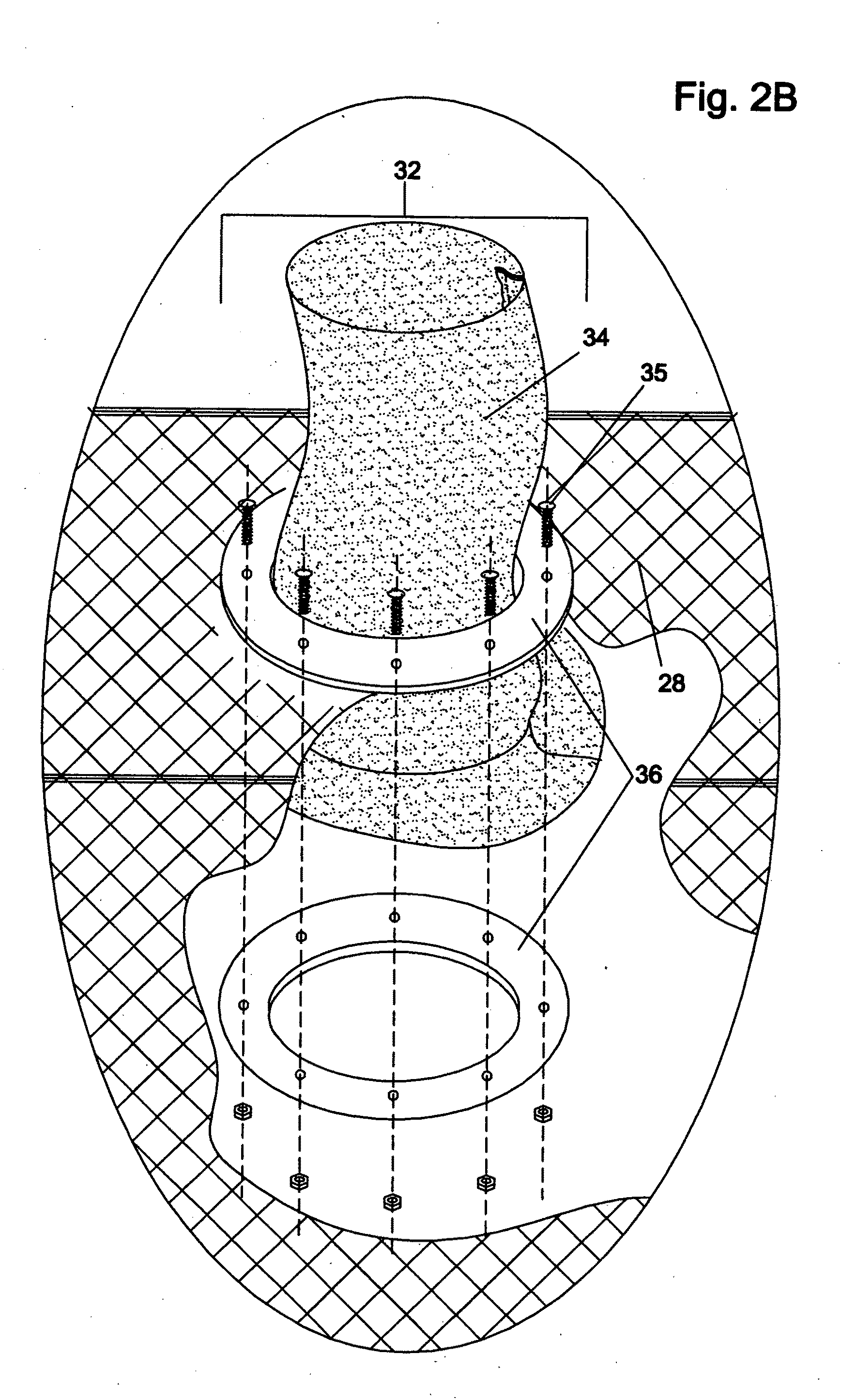
[0016]The filter bag is a closed top bag with a suitable fill port located at the top of the bag. The bottom of the bag would be left open and of sufficient length to hang below the framework by a suitable length. This framework would sit on top of a support system constructed of iron or concrete that would allow a transport vehicle to be positioned under the frame to allow the contents of the bag to gravity feed out of the bag and down into the hopper of the vehicle. At the bottom of the framework a set of doors or gates would be installed that will close around the open end of the filter bag. These doors would include an elastic seal that would compress around the bag effectively closing off the bottom of the bag to prevent leakage of solids out the bottom of the bag.
[0020]In a second embodiment of this method the filtration element would be fixed rigid panels installed inside the skeletal frame work. These panels could be manufactured from stainless steel, plastic or aluminum or other suitable material and would be permeable to allow the passage of free liquid while retaining the solids inside the filter. At the bottom of the frame work a set of doors would be installed that could be opened or closed. A seal would be installed between the bottom of the filter plates and the door to prevent leakage of solids. In this embodiment a set of rigid filter panels would also be installed across the top to form a closed container. The top would include a flanged port which would be connected to the fill pipe.

Problems solved by technology

Many of these are mechanical in nature and require a large amount of energy to operate and specialized skills to maintain.
Many of these devices work very well but all have the disadvantage of high operating and maintenance costs.
While this device may work well for some types of slurry it has a major disadvantage in that the dewatered material must be lifted out of the device to dispose or reprocess.
This limits the amount of material that can be effectively dewatered due to the weight of the dewatered material.
This device again has the limitation in that the volume of dewatered material would have to be limited to the weight limitations of the device.
Most dewatering processes require large volume and weight capabilities.
The disadvantages of this process include the handling expense of the consolidated solids and also the fact that these bags are laid out on the ground and are subject to weather related problems and drainage issues.
In addition the fact that the bag is positioned on the ground tends to blind off the bottom of the bag which is where the liquid is most likely to drain out.
That fact causes the liquid to pool up inside the bag and increases the drying time required to accomplish the dewatering phase.

Method used


Image

  • Method of dewatering solids laden liquids utilizing a reusable filter element
  • Method of dewatering solids laden liquids utilizing a reusable filter element
  • Method of dewatering solids laden liquids utilizing a reusable filter element

Examples


first embodiment

—FIRST EMBODIMENT

[0038]One embodiment of the bag retainer 10 and under carriage 14 is shown in FIG. 1. The frame work in this embodiment is constructed with (4) four vertical angle iron uprights 11. The uprights are connected with rectangular frames 12 that run horizontal around the structure. I contemplate these frames 12 to be heavy angle iron but they could be structural tubing or many other types of materials. In this embodiment there are (5) five of these frames 12. These frames 12 are spaced vertically down the structure to provide sufficient strength to retain the pressure created by the fluid column as the bag is filled. This embodiment has (6) six vertical bars 13 running from the top of the frame work to the bottom. These bars are in place to help prevent the bag from protruding out between the angle iron frames 12 as the bag is filling with fluid. Additional support bars can be used as needed to prevent this from occurring. The filter retainer 10 is fixed to the top of th...


PUM

PropertyMeasurementUnit
Pressureaaaaaaaaaa
Flow rateaaaaaaaaaa
Gravityaaaaaaaaaa

Abstract

A method of dewatering a solids laden waste stream, whereby the slurry is pumped into a vertical filter retaining structure and the liquid is allowed to flow out through the pores of the filtration element while retaining the solids within the structure. After the solids have dewatered, doors or gates located at the bottom of the structure are opened and the solids drop out the bottom by gravity. The structure is elevated to allow a transport vehicle to be placed under the doors prior to dropping out the solids. One embodiment utilizes an open bottom, closed top filter bag that is closed off by the doors or sliding gates located at the bottom of the structure. Another embodiment disclosed would use rigid filter plates to retain the solids and drop out the accumulated solids by opening sliding gates at the bottom of the structure. The filter bag or plates is accessible from the side to allow either manual or automatic pressure washing of the filtration elements or filter bag after each dewatering cycle.

Description

CROSS-REFERENCE TO RELATED APPLICATIONS[0001]This application claims the benefit of provisional patent application Ser. No. 60 / 997,714 filed Oct. 4, 2007 by the present inventor.FEDERALLY SPONSORED RESEARCH [0002]Not ApplicableSEQUENCE LISTING OR PROGRAM [0003]Not ApplicableBACKGROUND OF THE INVENTION[0004]1. Field[0005]This invention generally relates to the process of filtering the liquid from a solids laden slurry or waste material. More specifically, it is an improved method of separating the water from the solids and allowing the water to filter out leaving the solids inside the filter after which they can be extracted for disposal or reprocessing. The process is generally known as “dewatering” and is desirable in that it allows the solids to be reprocessed, transported or disposed of at a lower cost than a liquid.[0006]2. Prior Art[0007]There are many different types of “dewatering” apparatus in use today. Many of these are mechanical in nature and require a large amount of en...

Claims


Application Information

Patent Timeline
IPC IPC(8): B01D61/14
CPCB01D29/114B01D29/94
Inventor CONWELL, MICHAEL K.
Owner CONWELL MICHAEL K
Learn More