Brush seal device

a brush seal and sealing device technology, applied in the direction of engine seals, gas turbine plants, machines/engines, etc., can solve the problems of deteriorating yield rate, difficult assembly, and reducing the performance of the brush seal devi

Inactive Publication Date: 2009-12-24
EAGLE INDS
View PDF6 Cites 38 Cited by
  • Summary
  • Abstract
  • Description
  • Claims
  • Application Information

AI Technical Summary

Problems solved by technology

In addition, when the rotary body has a large diameter, a brush seal device will have larger diameter in response to that, thus a yield rate deteriorates because the brush seal device is cut out from the material including the dimension of this large diameter.
Further, since the large size brush seal device is heavy weight articles, it is necessary to assemble by hanging using a crane and the like which would be difficult to assemble.
However, when a pressure of the sealing fluid acts to the divide...

Method used


Image

  • Brush seal device
  • Brush seal device
  • Brush seal device

Examples


first embodiment

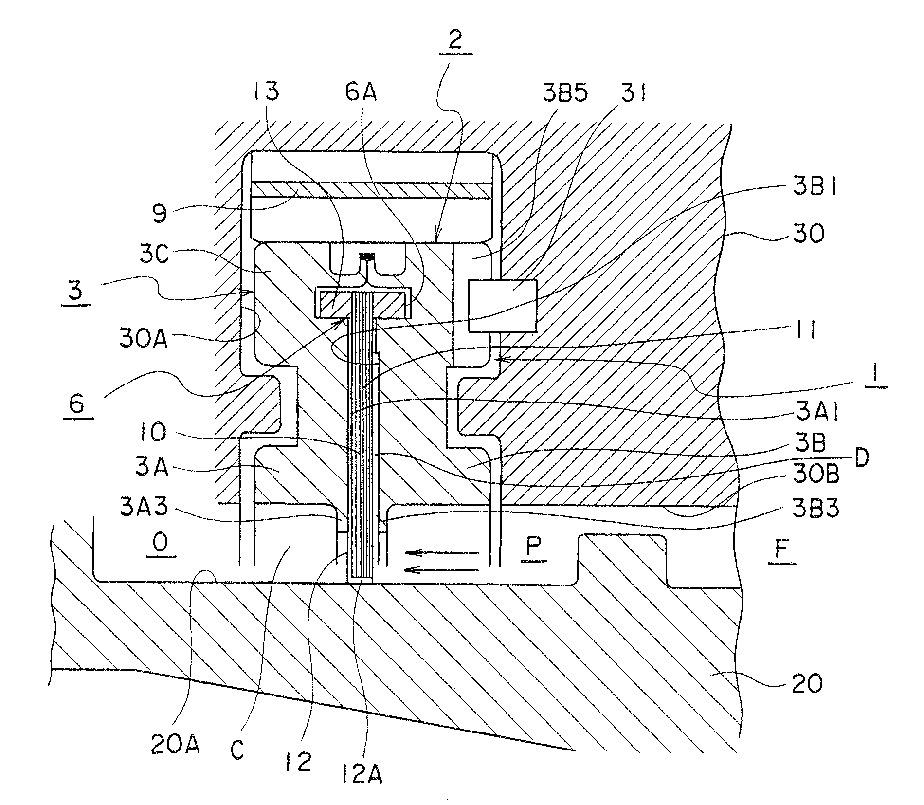
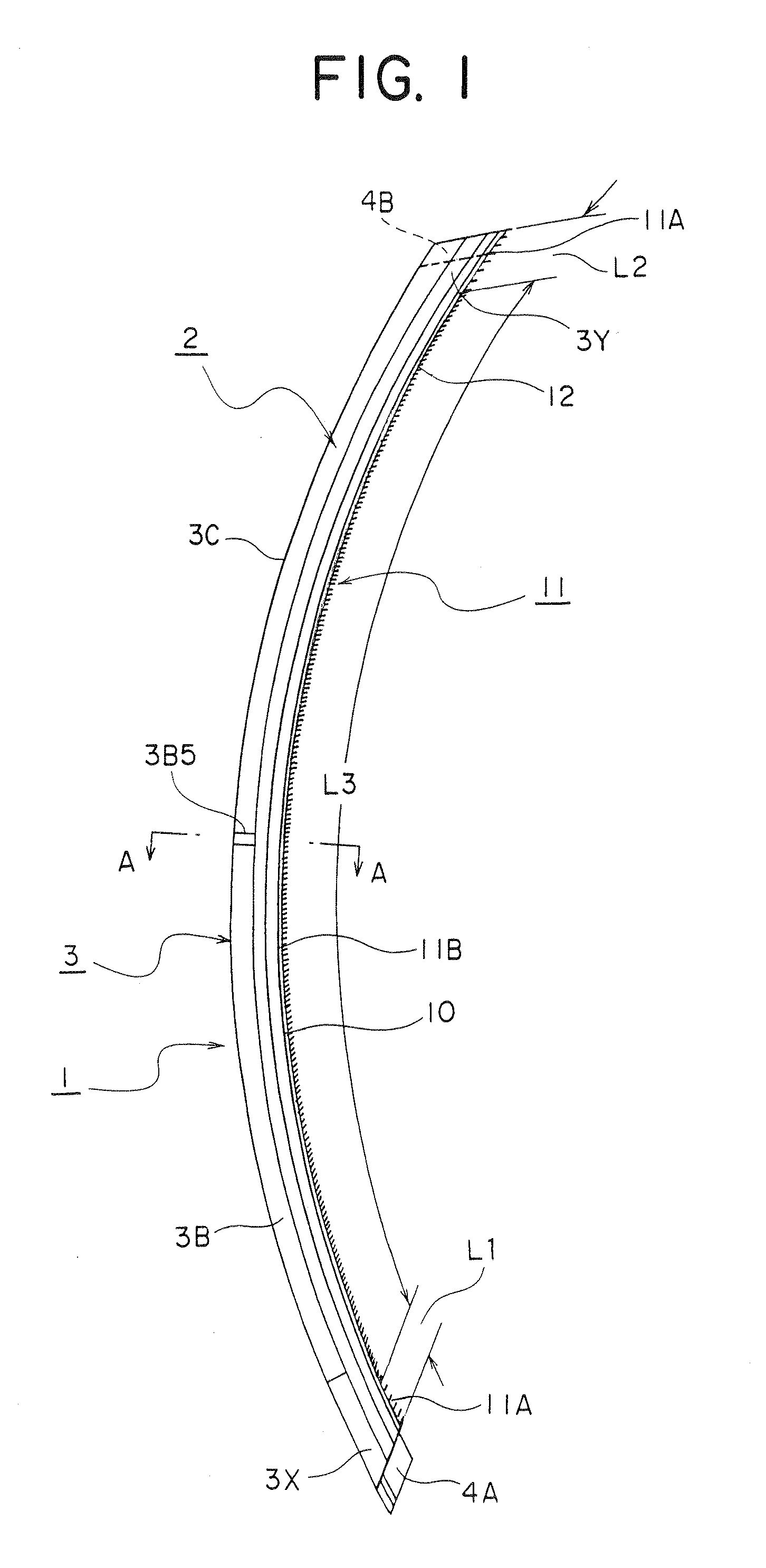
[0078]This brush seal device seals, for example, the leaking of the high temperature and high pressure fluid, or cooling air from a gap between a stationary component and a rotary component. A brush seal of a preferred embodiment according to the present invention will be described. FIG. 1 shows one of divided brush seals 2 divided from a brush seal device 1. FIG. 2 is a front view viewing from an inner circumferential side of a connecting portion R of the two divided brush seals 2, 2 in the brush seal device 1. FIG. 4 is a cross sectional view along a line A-A of FIG. 1 when the brush seal device 1 is mounted to assembly components. This brush seal device 1 is formed in a ring shape by connecting first and second end portions 3X, 3Y of the divided brush seals 2. And, for example, in order to seal a gap C between the components of a turbine engine as shown in FIG. 4, the brush seal device 1 is equipped.

[0079]A rotor assembly 20 of the assembly components in the turbine engine is hel...

second embodiment

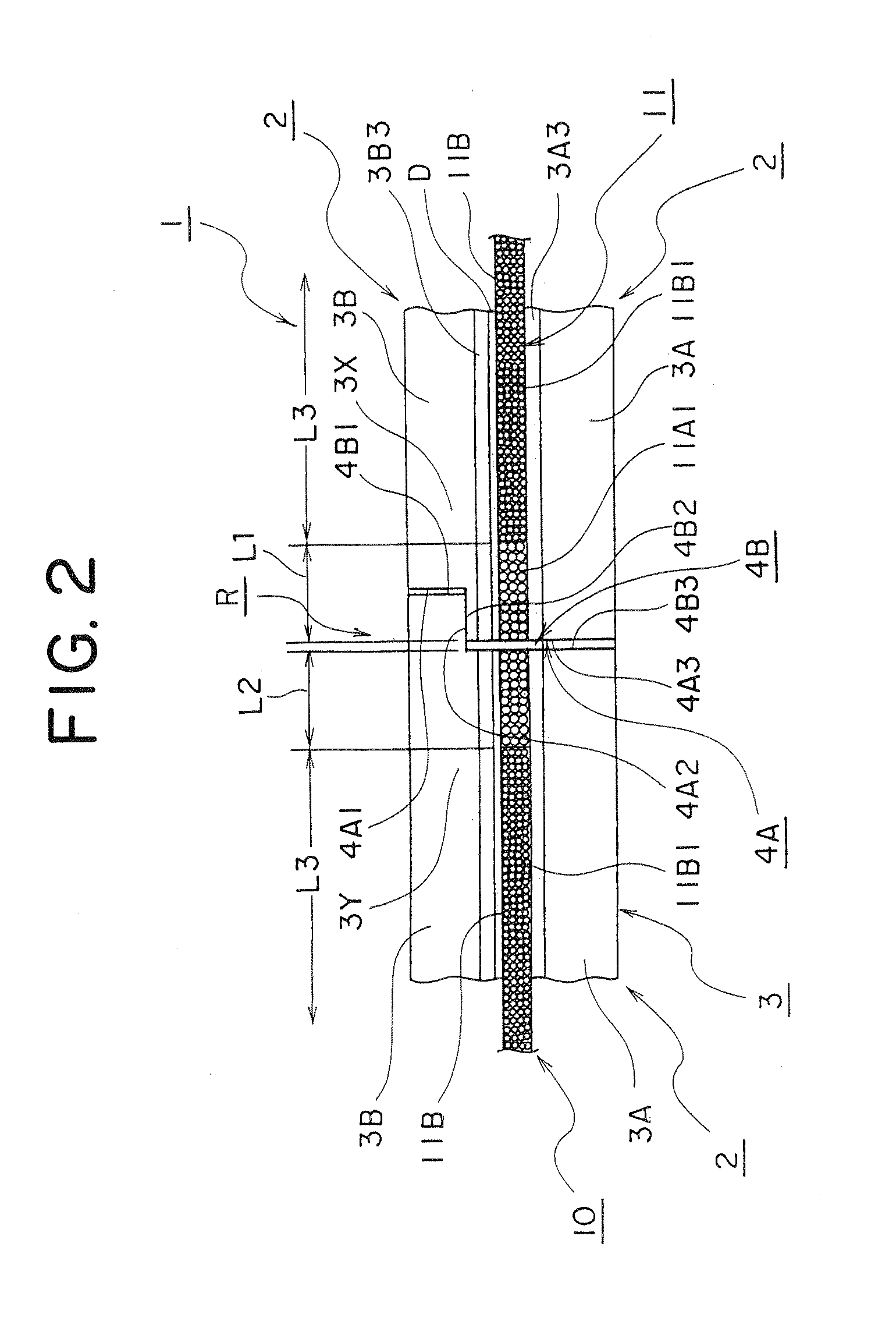
[0089]FIG. 3 is a cross sectional view showing a connecting portion R of a brush seal device 1 of a second embodiment according to the present invention. This connecting portion R of a first connecting face 4A and a second connecting face 4B is divided towards an axial direction inclined towards a circumferential direction of the brush seal device 1. Note that, in this connecting portion R, the a first length range L1 of a first bristle layer 11A of a first end portion 3X and a second length range L2 of a first bristle layer 11A of a second end portion 3Y may be formed within a range of 7 mm to 25 mm from the inner circumferential end faces of a first connecting face (end face) of the first bristle layer 11A of the first connecting face 4A side and a second connecting face (end face) of the first bristle layer 11A of the second connecting face 4B side to an inner circumferential direction of a second bristle layer 11B, respectively. More preferably, the first length range L1 and the...

third embodiment

[0091]FIG. 8 is a cross sectional view of a brush seal device 1 of a third embodiment according to the present invention. In FIG. 8, a different point from FIG. 4 is that it is possible to make an inner radial face 3A2 of a first seal plate 3A3 of a supporting plate 3A close to an outer circumferential face 20A of a rotor assembly 20 by making the inner radial face 3A2 of the first seal plate portion 3A3 of the supporting plate 3A smaller than an inner radial face 3B2 of a second seal plate 3B3 of a holding plate 3B. By this first seal plate portion 3A3, a seal portion 12 of a seal brush 10 can be supported strongly against a pressure of the sealing fluid. As a result of this, swinging of the seal brush 10 due to the fluctuating pressure of the sealing fluid can be prevented. Also, when a second bristle layer 11B tries to contact with a rotation member, it effectively prevents the wearing of a contact portion by the elastic deformation in response to a force of the tip side while su...


PUM


Abstract

A divided brush seal comprises a base portion to shut off a sealing fluid side area and environment area, a first end portion having a first connecting face at one side divided end of the base portion, a second end portion having a second connecting face at another divided end of the base portion which connects with the first end portion, a seal brush having bristle groups to seal the sealing fluid provided parallel to a supporting face with coupling one end thereof to a fixed portion which connects with the base plate, wherein the first end portion and the second end portion comprise a first bristle groups respectively, a wire diameter of a first bristle of the first bristle groups is thicker with respect to a wire diameter of a second bristle of a second bristle groups provided between the first bristle group of the first end portion and the first bristle group of the second end portion, the first bristle group of the respective divided brush seal and the first bristle group of the other side divided brush seal adjacent thereto are sequentially arranged.

Description

FIELD OF THE INVENTION[0001]This invention relates to a brush seal device to seal between a fixed component and a relative moving component of assembling portion of an engine or a power generation gas turbine engine. More particularly, the present invention relates to a brush seal device to prevent the abrasion of a seal brush by a sealing fluid which acts between connecting spaces of a divided portion in a brush seal device which tightly connects the divided portion.BACKGROUND OF THE INVENTION[0002]For example, when a ring shape brush seal device is assembled between bearings of a steam turbine, it is necessary to remove a rotary body and the bearings to assemble the brush seal device. In addition, when the rotary body has a large diameter, a brush seal device will have larger diameter in response to that, thus a yield rate deteriorates because the brush seal device is cut out from the material including the dimension of this large diameter. Further, since the large size brush seal...

Claims


Application Information

Patent Timeline
IPC IPC(8): F16J15/44
CPCF01D11/003F05D2240/56F16J15/3288F02C7/28
Inventor KASAHARA, HIDETOSHIKONO, TORU
Owner EAGLE INDS
Why Eureka
Try Eureka