Image display apparatus and driving method thereof, and image display apparatus assembly and driving method thereof

a technology of image display and driving method, which is applied in the direction of instruments, television systems, and television system scanning details, can solve problems such as color dullness, and achieve the effects of raising not only luminance, high degree of reliability, and reducing the number of display devices

Active Publication Date: 2009-12-24
JAPAN DISPLAY WEST
View PDF7 Cites 73 Cited by
  • Summary
  • Abstract
  • Description
  • Claims
  • Application Information

AI Technical Summary

Benefits of technology

[0068]As a result of extending the output signal values X1-(p, q), X2-(p, q), X3-(p, q) and X4-(p, q) on the basis of the extension coefficient α0 as described above, the luminance of the white-color display sub-pixel increases in the same way as the existing technology. Unlike the existing technology, however, there is no case in which the luminance of the red-color display sub-pixel, the luminance of the green-color display sub-pixel or the luminance of the blue-color display sub-pixel does not increase. That is to say, the image display apparatus or the methods for driving the image display apparatus and the image display apparatus assembly or the method for driving the image display apparatus assembly raise not only the luminance of the white-color display sub-pixel but also the luminance of the red-color display sub-pixel, the luminance of the green-color display sub-pixel or the luminance of the blue-color display sub-pixel. Therefore, the image display apparatus or th

Problems solved by technology

Thus, the technologies raise a probl

Method used


Image

  • Image display apparatus and driving method thereof, and image display apparatus assembly and driving method thereof
  • Image display apparatus and driving method thereof, and image display apparatus assembly and driving method thereof
  • Image display apparatus and driving method thereof, and image display apparatus assembly and driving method thereof

Examples


first embodiment

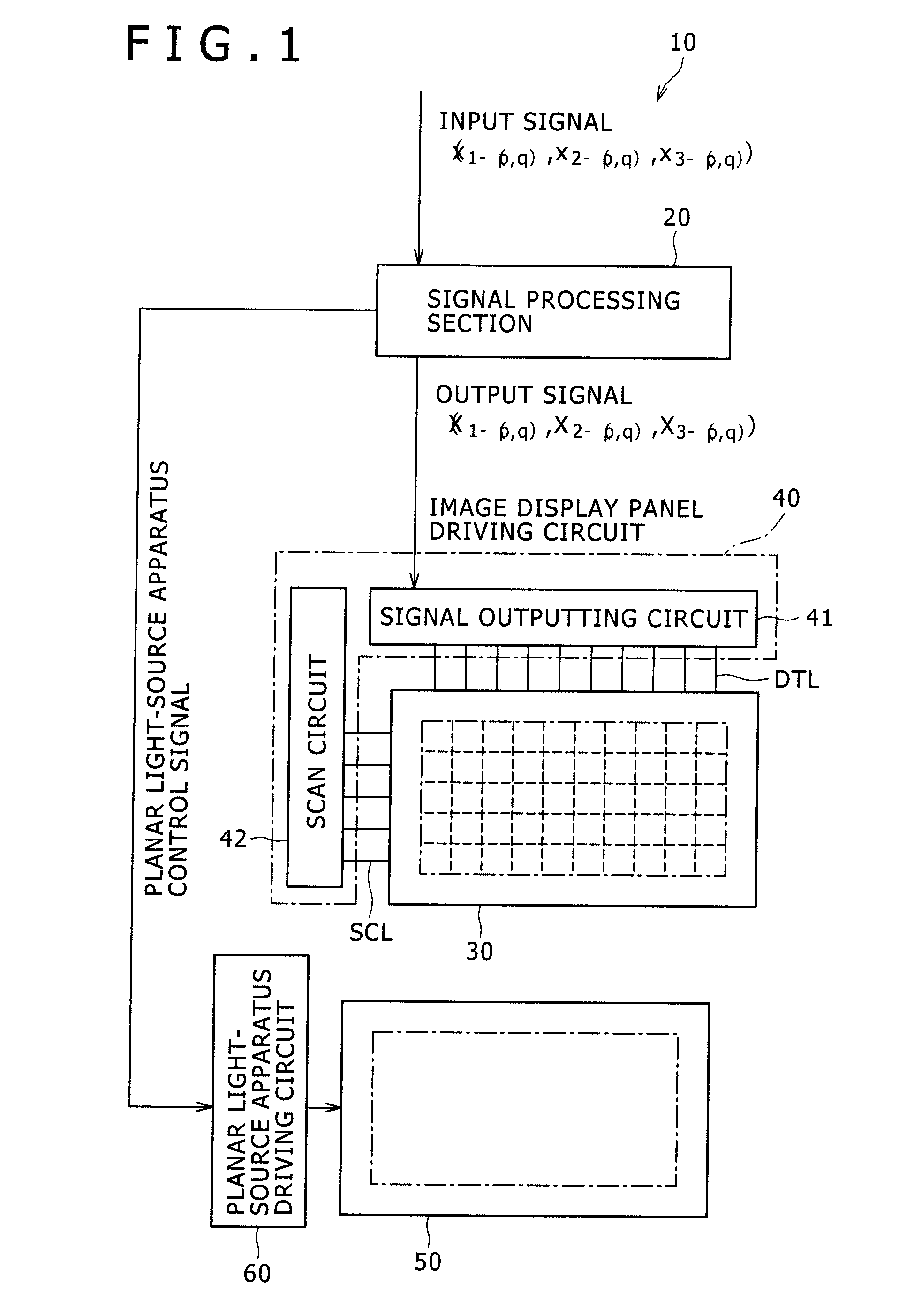
[0141]A first embodiment implements an image display apparatus 10 according to a first form of the present invention, a method for driving the image display apparatus 10, an image display apparatus assembly employing the image display apparatus 10 and a method for driving the image display apparatus assembly.

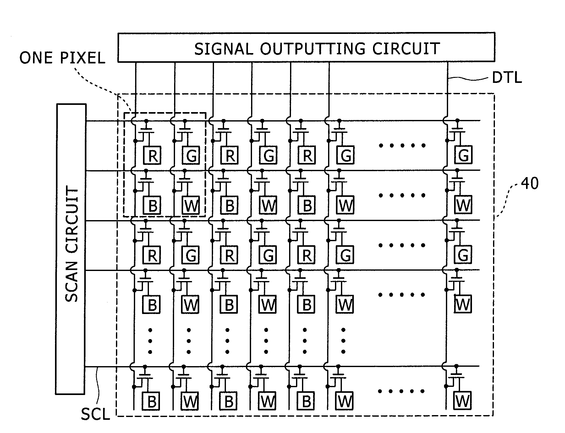
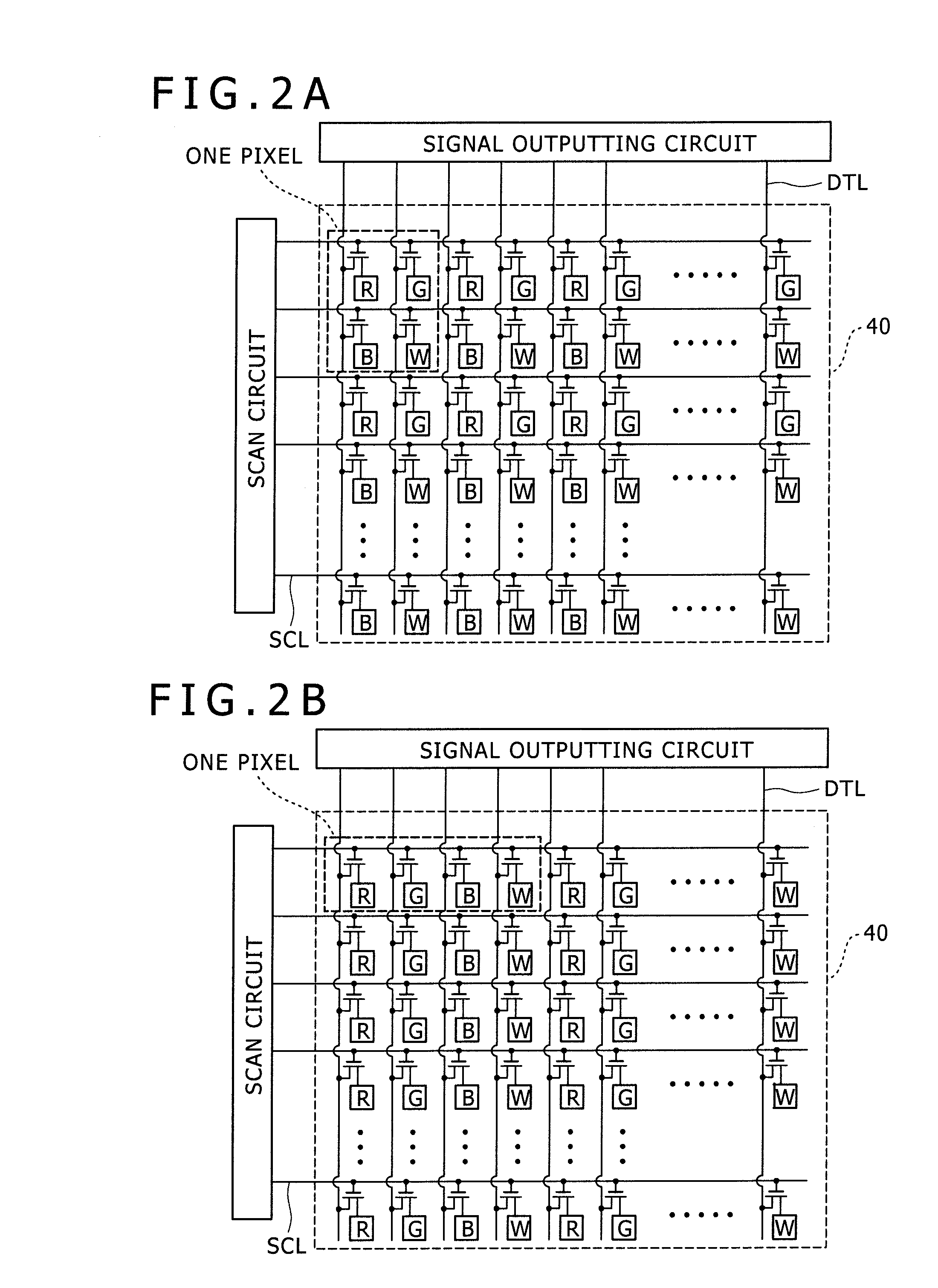
[0142]As shown in a conceptual diagram of FIG. 1, the image display apparatus 10 according to the first embodiment employs a image display panel 30 and a signal processing section 20. The image display apparatus assembly according to the first embodiment employs the image display apparatus 10 and a planar light-source apparatus 50 for radiating illuminating light to the rear face of the image display apparatus 10. To put it more concretely, the planar light-source apparatus 50 is a section for radiating illuminating light to the rear face of the image display panel 30 employed in the image display apparatus 10. As shown in conceptual diagrams of FIGS. 2A and 2B, the image displa...

second embodiment

[0187]A second embodiment is obtained by modifying the first embodiment. Even though the planar light-source apparatus of the right-below type in the past can be employed as the planar light-source apparatus, in the case of the second embodiment, a planar light-source apparatus 150 of a division driving method (or a portion driving method) to be described below is employed. It is to be noted that the extension process itself is the same as the extension process of the first embodiment described above.

[0188]In the case of the second embodiment, it is assumed that the display area 131 of the image display panel 130 composing the color liquid-crystal display apparatus is divided into S×T virtual display area units 132 as shown in a conceptual diagram of FIG. 8. The planar light-source apparatus 150 of a division driving method has S×T planar light-source units 152 which are each associated with one of the S×T virtual display area units 132. The light emission state of each of the S×T v...

third embodiment

[0217]A third embodiment is also obtained as a modified version of the first embodiment. The third embodiment implements an image display apparatus which is explained as follows. The image display apparatus according to the third embodiment employs an image display panel created as a two-dimensional matrix of light emitting device units UN each having a first light emitting device corresponding to a first sub-pixel for emitting a red color, a second light emitting device corresponding to a second sub-pixel for emitting a green color, a third light emitting device corresponding to a third sub-pixel for emitting a blue color and a fourth light emitting device corresponding to a fourth sub-pixel for emitting a white color. The image display panel employed in the image display apparatus according to the third embodiment is typically an image display panel having a configuration and a structure which are described below. It is to be noted that the number of aforementioned light emitting ...


PUM


Abstract

An image display apparatus includes: an image display panel having a two-dimensional matrix with (P×Q) pixels each including first, second and third sub-pixels for displaying respective first, second and third elementary colors, and fourth sub-pixel for displaying a fourth color; and a signal processing section configured to receive first, second and third sub-pixel input signals respectively provided with signal values of x1-(p, q), x2-(p, q) and x3-(p, q), and to output first, second, third and fourth sub-pixel output signals respectively provided with signal values of X1-(p, q), X2-(p, q), X3-(p, q) and X4-(p, q), which used for determining the display gradations of the first, second, third, and fourth sub-pixels, respectively, with regard to a (p, q)th pixel where notations p and q are integers satisfying equations 1≦p≦P and 1≦q≦Q.

Description

BACKGROUND OF THE INVENTION[0001]1. Field of the Invention[0002]The present invention relates to an image display apparatus, a driving method of the image display apparatus, an image display apparatus assembly employing the image display apparatus and a driving method of the image display apparatus assembly.[0003]2. Description of the Related Art[0004]In recent years, in the case of an image display apparatus such as a color liquid-crystal display apparatus for example, the increased performance raises a problem of the increased power consumption. In particular, with the improved fineness, the widened color reproduction range and the increased luminance, in the case of the color liquid-crystal display apparatus for example, the power consumption of the backlight undesirably rises. In order to solve these problems, attention is paid to a technology for improving the luminance of the display by making use of a white-color display sub-pixel for displaying a white color. In accordance w...

Claims


Application Information

Patent Timeline
IPC IPC(8): G09G5/02G09G3/36
CPCG09G3/001G09G3/2003G09G3/3208G09G3/3413G09G3/3426G09G2360/142G09G2300/0452G09G2320/0242G09G2320/064G09G2320/0666G09G2340/06G09G3/3611G02F1/133G09G3/20G09G3/36
Inventor SAKAIGAWA, AKIRAIIJIMA, YUKIKOHIGASHI, AMANENOGUCHI, KOJI
Owner JAPAN DISPLAY WEST
Why Eureka
Try Eureka