Liquid ejection head

a liquid ejection head and ejection head technology, applied in the direction of printing, inking apparatus, etc., can solve the problems of inability to produce bubbles, unstable bubble generation, uneven heat transfer from the heating resistor to the ink, etc., to achieve the effect of removing cogation matters and improving adhesion

Active Publication Date: 2009-12-24
CANON KK
View PDF7 Cites 21 Cited by
  • Summary
  • Abstract
  • Description
  • Claims
  • Application Information

AI Technical Summary

Benefits of technology

[0015]The object of the present invention is to provide a reliable liquid ejection head which, even if matters caused by cogation accumulates on a prote

Problems solved by technology

When a hardly-soluble organic matter or inorganic matter is adsorbed onto the protective layer due to the cogation, the transfer of heat from the heating resistor to the ink becomes uneven and the bubble generation becomes unstable.
Then, this type of high temperature thermal action gives rise to the problem of cogation occurring.
In response to this problem, there are conventionally known countermeasures which make it difficult for cogation to occur by using ink containing a dye with a high heat resistance, or by using ink in which the amount of impurities in the dye is reduced by carrying out a sufficient refining.
However, there are problems in that the manufacturing cost of the ink increases accordingly, the types of dye which can be used are limited, and the like.
However, although the method described in Japanese Patent Laid-Open No. 2008-105364 can effectively remove the cogation, regarding the above described protective layer formed on the head substrate, there is a difficulty relating to adhesion of the protective layer with a resin layer of a path wall or the like which are formed on the protective layer.
As a result, a problem develo

Method used


Image

  • Liquid ejection head
  • Liquid ejection head
  • Liquid ejection head

Examples


Embodiment Construction

)

[0029]Hereafter, a detailed description of embodiments of the present invention will be given referring to the drawings.

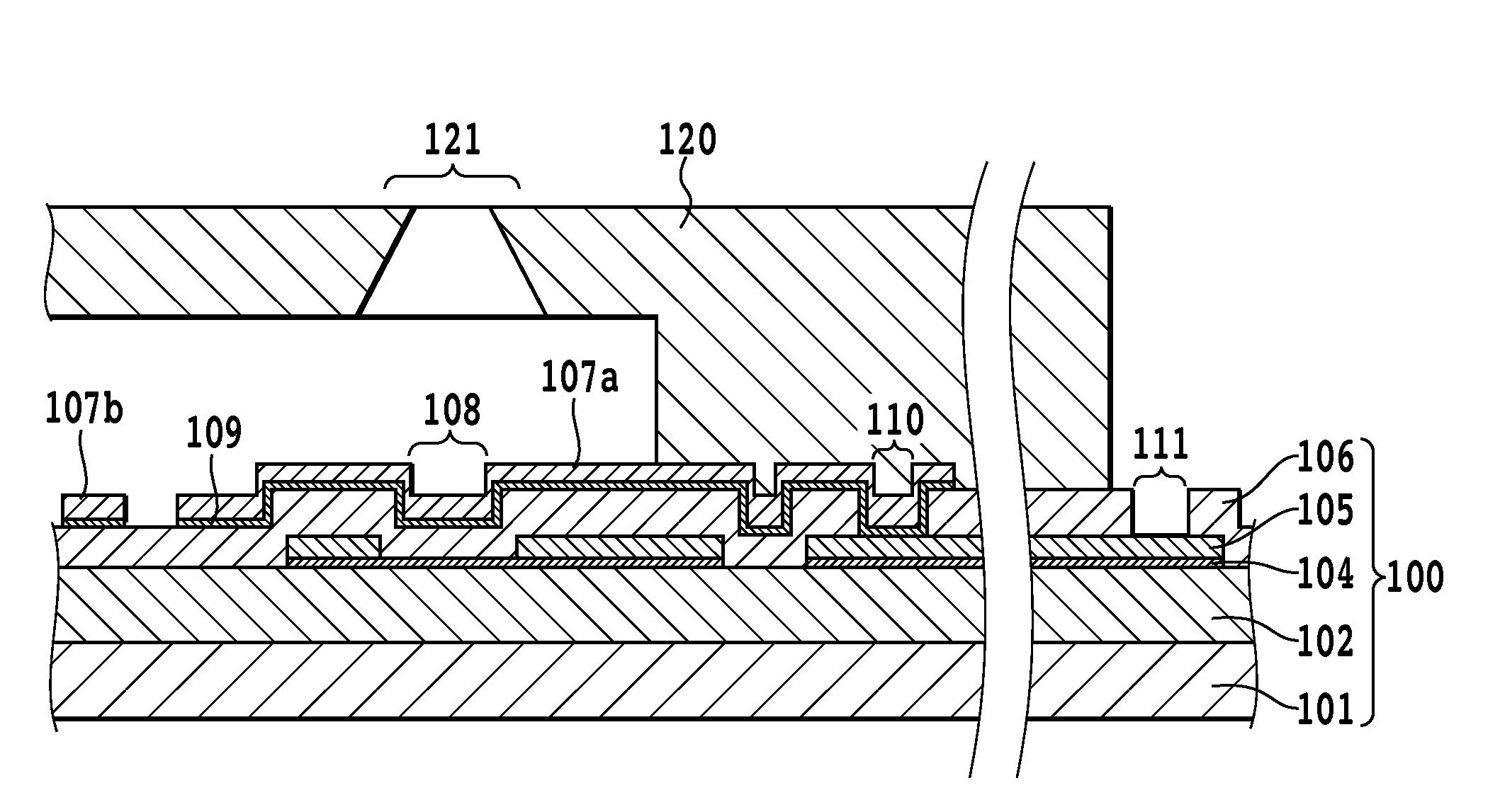
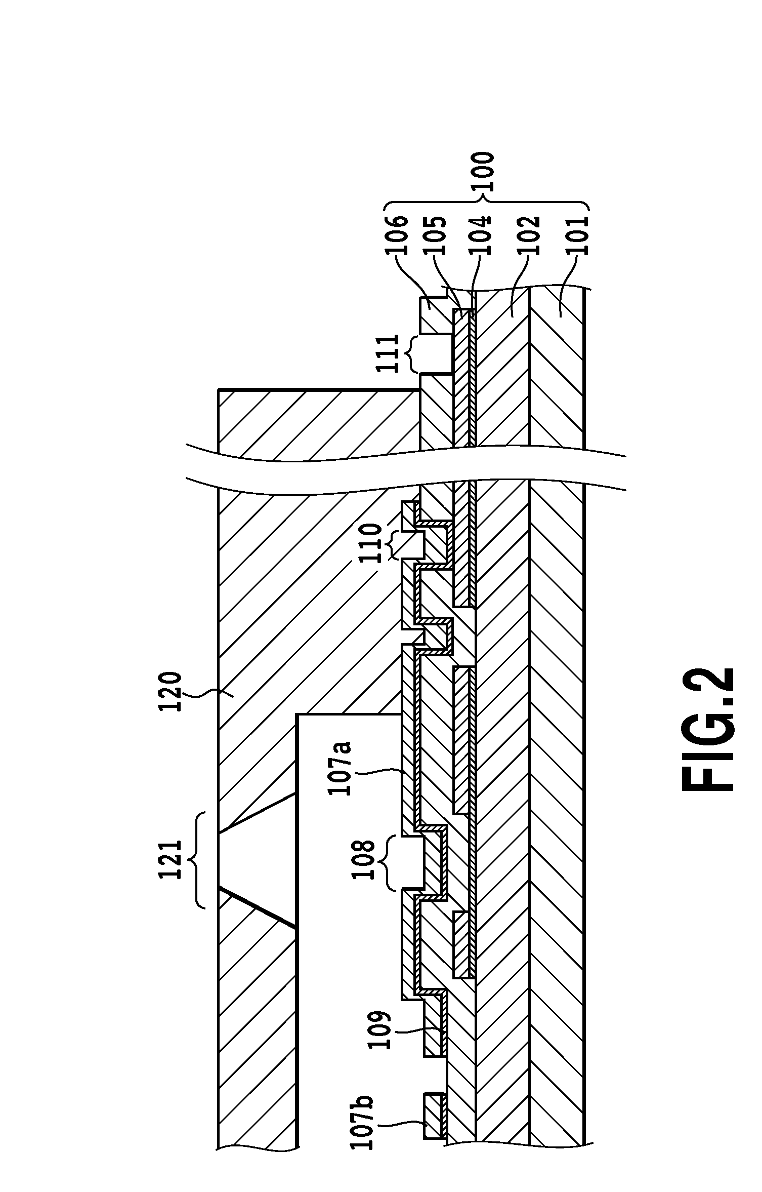
[0030]FIG. 2 is a schematic partial sectional view showing an ink jet head to which a configuration of the present invention is applied. Also, FIG. 3 is a schematic plan view of the vicinity of a heat application portion in an ink jet head substrate according to the embodiment of the invention. FIG. 2 is a sectional view showing a state of the substrate that is cut vertically along a line II-II in FIG. 3.

[0031]In FIGS. 2 and 3, a reference numeral 101 denotes a silicon substrate. A reference numeral 102 denotes a thermal storage layer which can be formed of a thermally oxidized film, a silicon monoxide (SiO) film, a silicon nitride (SiN) film, or the like. A reference numeral 104 denotes an heating resistor layer, and a reference numeral 105 denotes an electrode wiring layer, which acts as wiring and is formed of a metal material such as aluminum, aluminum-silicon...


PUM


Abstract

On the liquid ejection head substrate, an upper protective layer, as well as coming into contact with the resin layer which configures a path forming member such as a ejection opening, comes into contact with ink in an heat generating portion inside the channel formed. The upper protective layer contains iridium and silicon. The upper protective layer is configured so that, at a surface in contact with the ink and resin layer, Ir100-xSix attains a 15 at. %≦X≦30 at. % silicon content rate, and that X more becomes zero as a position in the upper protective layer more approaches an adhesion layer. As a result, at the interface where the upper protective layer comes into contact with the path forming member, by the silicon attaining the heretofore described content rate, it is possible to improve the adhesion with the path forming member made of resin compared with a case of using iridium alone.

Description

BACKGROUND OF THE INVENTION[0001]1. Field of the Invention[0002]The present invention relates to a liquid ejection head which ejects a liquid, and particularly relates to a layer which protects an heat generating portion in a liquid ejection head which ejects a liquid utilizing thermal energy.[0003]2. Description of the Related Art[0004]An ink ejection method described in U.S. Pat. No. 4,723,129, and in U.S. Pat. No. 4,740,796, is a method which ejects ink by utilizing thermal energy to cause an air bubble to form in the ink, and therefore enables a high speed, high image quality printing. Also, as this method is appropriate for colorization and downsizing, in recent years it has become a mainstream ink jet printing method.[0005]A general configuration of a liquid ejection head using this method is one which includes a plurality of ejection openings, liquid paths communicating with the ejection openings, and electro-thermal converting elements which generate thermal energy utilized ...

Claims


Application Information

Patent Timeline
IPC IPC(8): B41J2/05
CPCB41J2/14129B41J2/1603B41J2/1628B41J2/1631B41J2202/03B41J2/1634B41J2/1645B41J2/1646B41J2/1632
Inventor SAKURAI, MAKOTOSAITO, ICHIRO
Owner CANON KK
Why Eureka
Try Eureka