
Photonic bandgap fiber

a bandgap fiber and bandgap technology, applied in the field of photonic bandgap fiber, can solve problems such as beam quality degradation, and achieve the effects of reducing the propagation loss of the fundamental mode and increasing the propagation loss of the higher-order mod

Active Publication Date: 2009-12-24
THE FUJIKURA CABLE WORKS LTD
View PDF9 Cites 4 Cited by
  • Summary
  • Abstract
  • Description
  • Claims
  • Application Information

AI Technical Summary

Benefits of technology

[0018]According to the photonic bandgap fiber of the invention, the periodic structure portion is provided around the first and second cores. Therefore, it is possible to reduce the propagation loss of the fundamental mode, and to increase the propagation loss of the higher-order modes whose propagation needs to be suppressed.
[0019]According to the photonic bandgap fiber of the invention, the refractive index of the first core is equal to or smaller than the refractive index of the cladding, and the refractive index of the second core is smaller than the refractive index of the cladding. Therefore, the guiding principle is based on the photonic bandgap effect, thus, in principle, a phenomenon in which the electrical field of a mode propagating in the core couples to a mode propagating in the periodic structure portion and then recouples to a mode propagating in the core does not occur. As a result, an effect of filtering higher-order modes can be higher.

Problems solved by technology

The propagation of the higher-order modes may cause deterioration of beam quality.

Method used


Image

  • Photonic bandgap fiber
  • Photonic bandgap fiber
  • Photonic bandgap fiber

Examples


example 1

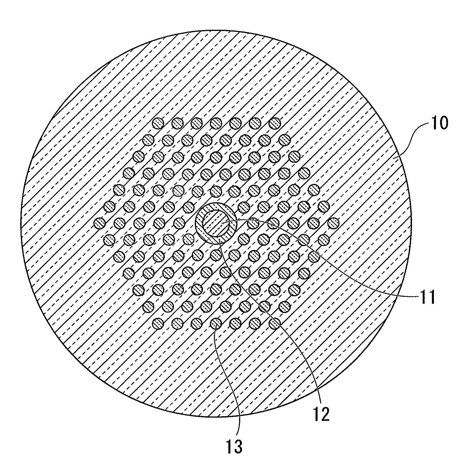
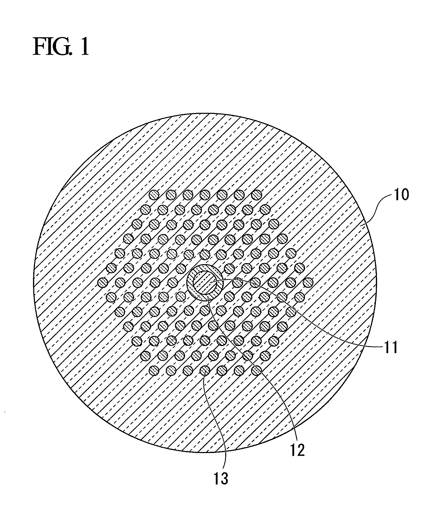
[0058]As an example of the invention, a photonic bandgap fiber having a structure shown in FIG. 1 is manufactured. Within a cladding 10 made of pure quartz glass having a refractive index of 1.45, a first core 11 having a relative refractive-index difference Δ1 of 0% with respect to the cladding 10 and a diameter d1 of 17.8 μm is provided. A second core 12 having a relative refractive-index difference Δ2 of −0.36% with respect to the cladding 10 and a diameter d2 of 25 μm is provided around the first core 11. High-refractive index portions 13 having a relative refractive-index difference Δh of 1.6% with respect to the cladding 10 and a diameter dh of 5.6 μm are provided around the second core 12 to form a periodic structure which is a triangular lattice structure having a period of 14.0 μm (periodic structure portion). In the periodic structure, two layers at the center are not provided in order to form a core, and a five-layered periodic structure is formed.

[0059]FIG. 3 illustrates...

example 2

[0065]As another example of the invention, a photonic bandgap fiber having a structure shown in FIG. 10 was prepared. Within a cladding 100 made of pure quartz glass having a refractive index of 1.45, a first core 101 having a relative refractive-index difference Δ1 of 0.0% with respect to the cladding 100 and a diameter d1 of 12.0 μm is provided. A second core 102 having a relative refractive-index difference Δ2 of −0.36% with respect to the cladding 100 and a diameter d2 of 22.0 μm is provided around the first core 101. High-refractive index portions 103 having a relative refractive-index difference Δh of 1.6% with respect to the cladding 100 and a diameter dh of 3.2 μm are arranged around the second core 102 to form a periodic structure which is a triangular lattice structure having a period of 9.0 μm (periodic structure portion). In the periodic structure, two layers at the center are not provided in order to form a core, and a five-layered periodic structure is formed.

[0066]The...

example 3

[0068]As another example of the invention, a photonic bandgap fiber having a structure shown in FIG. 12 was prepared. Within a cladding 120 made of pure quartz glass having a refractive index of 1.45, a first core 121 having a relative refractive-index difference Δ1 of 0.0% with respect to the cladding 120 and a diameter d1 of 29.0 μm is provided. A second core 122 having a relative refractive-index difference Δ2 of −0.36% with respect to the cladding 120 and a diameter d2 of 35.0 μm is provided around the first core 121. High-refractive index portions 123 having a relative refractive-index difference Δh of 1.6% with respect to the cladding 120 and a diameter dh of 5.8 μm are arranged around the second core 122 to form a periodic structure which is a triangular lattice structure having a period of 14.5 μm (periodic structure portion). In the periodic structure, two layers at the center are not provided in order to form a core, and a five-layered periodic structure is formed.

[0069]FI...


PUM


Abstract

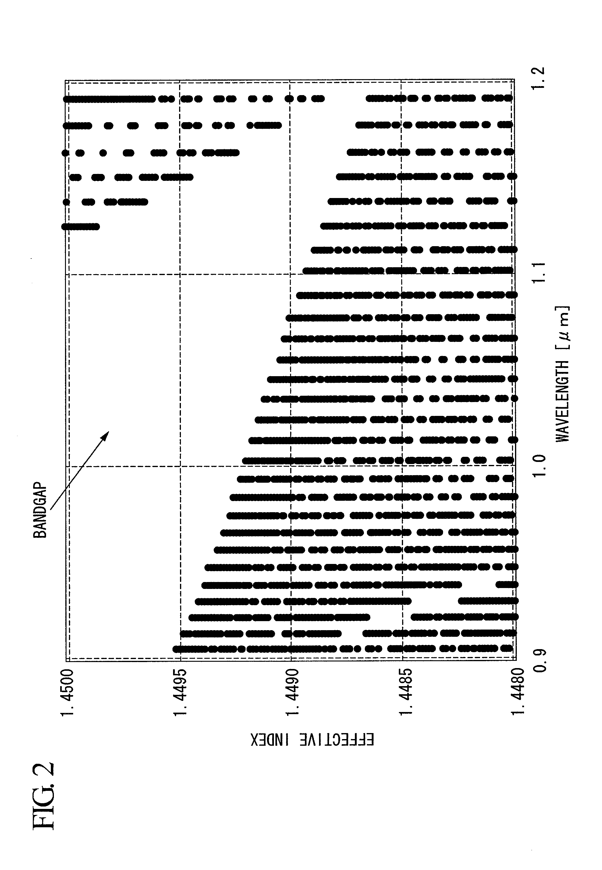
A photonic bandgap fiber includes a first core having a refractive index equal to or smaller than a refractive index of a cladding, a second core that is provided to surround the first core and has a refractive index smaller than the refractive index of the first core, the cladding that surrounds the second core, and a periodic structure portion that is provided in the cladding around the second core, and in which high-refractive index portions having a refractive index larger than the refractive index of the cladding form a periodic structure. The periodic structure is configured such that at least the propagation constant of the fundamental mode at a wavelength to be used is in a photonic bandgap, and the propagation constant of a higher-order mode at the wavelength to be used is outside of the photonic bandgap.

Description

TECHNICAL FIELD[0001]The present invention relates to a photonic bandgap fiber, in particular, to a photonic bandgap fiber having a function to suppress propagation of higher-order modes.[0002]Priority is claimed on Japanese Patent Application No. 2007-54273, filed Mar. 5, 2007, and Japanese Patent Application No. 2007-149181, filed Jun. 5, 2007, the contents of which are incorporated herein by reference.BACKGROUND ART[0003]In recent years, a high-power fiber laser using a rare-earth-doped fiber has been attracting public attention. The high-power fiber laser is configured such that, while pump light and signal light are propagating through a fiber, the signal light is amplified by the pump light. The high-power fiber laser has advantages such as ease of cooling and reduction in size.[0004]In such a high-power fiber laser, in order to suppress nonlinear effects, a fiber having a large mode field diameter (MFD) is used. However, if the mode field diameter is simply increased, higher-...

Claims


Application Information

Patent Timeline
Patent Type & Authority Applications(United States)
IPC IPC(8): G02B6/036
CPCG02B6/02323G02B6/02338G02B6/02347H01S3/302G02B6/03644H01S3/06741G02B6/0238
Inventor GOTO, RYUICHIRO
Owner THE FUJIKURA CABLE WORKS LTD
Learn More