Implantable fluid management device for the removal of excess fluid

a fluid management device and fluid management technology, applied in the direction of infusion syringes, automatic syringes, intravenous devices, etc., can solve the problems of inability to effectively meet the oxygen needs of other organs, use of external catheters, and further fluid accumulation, so as to promote the flow of fluid

Active Publication Date: 2009-12-24
SEQUANA MEDICAL NV
View PDF100 Cites 79 Cited by
  • Summary
  • Abstract
  • Description
  • Claims
  • Application Information

AI Technical Summary

Benefits of technology

[0016]In one embodiment, the first and second elements are each shaped like expandable disks having circumferential perimeters one parallel to the other, and the annular surface is disposed parallel to the first and second elements. Recesses are disposed radially on the outer face of the

Problems solved by technology

One such conditions is congestive heart failure (CHF), which causes the heart to be unable to effectively meet the oxygen needs of other organs.
These compensatory changes burden the cardiac function, leading to progressive CHF.
Fluid and salt restrictions may be imposed, but despite these measures, most patients continue to accumulate fluid with cardiac function deteriorating over time, which results in further fluid accumulation until the patient receives a heart transplant or succumbs

Method used


Image

  • Implantable fluid management device for the removal of excess fluid
  • Implantable fluid management device for the removal of excess fluid
  • Implantable fluid management device for the removal of excess fluid

Examples


Embodiment Construction

[0034]Detailed descriptions of embodiments of the invention are provided herein. It is to be understood, however, that the present invention may be embodied in various forms. Therefore, the specific details disclosed herein are not to be interpreted as limiting, but rather as a representative basis for teaching one skilled in the art how to employ the present invention in virtually any detailed system, structure, or manner.

[0035]The present invention concerns a device and a related method for removing fluid from a body cavity. An excessive drainage of fluid may be prevented by coupling an uptake tube to a reservoir constructed as described hereinbelow.

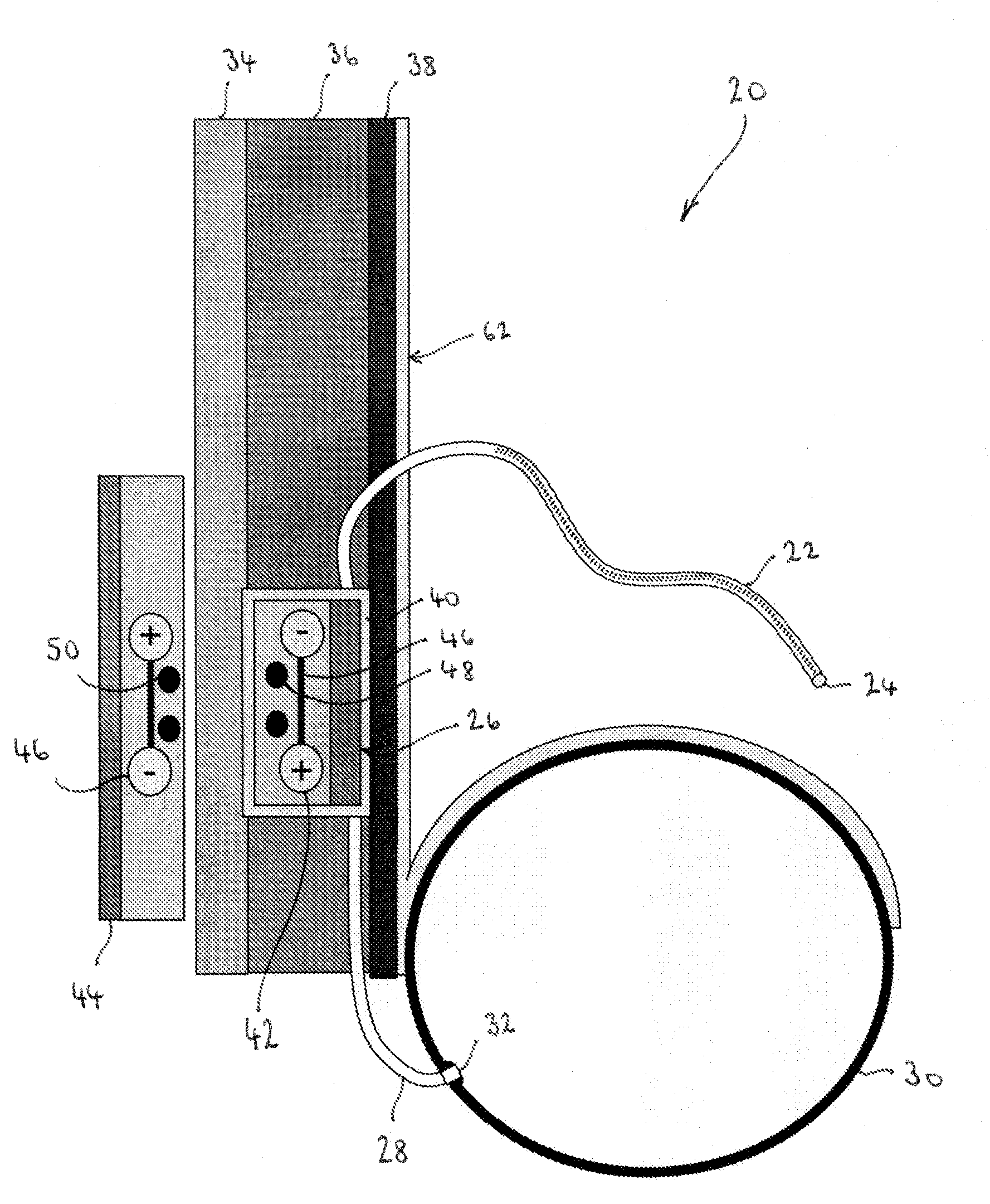
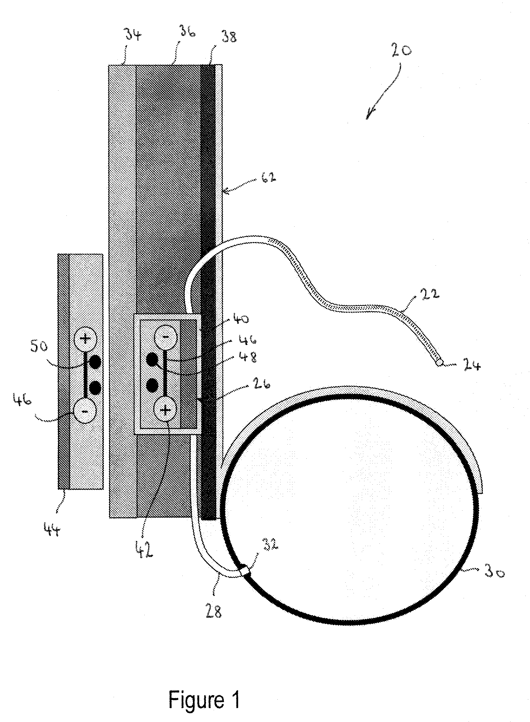
[0036]FIG. 1 illustrates a first embodiment of a device 20 from removing excess fluid from a body region. Device 20 may be utilized, for example, to remove excess fluid from the space between the lungs and the chest wall. Fluid accumulated in this area, called the pleural space, may lead to various diseases or disorders, such as CHF, l...


PUM


Abstract

A device for removing fluid from a first bodily cavity and for directing that fluid into a second bodily cavity while avoiding risks of infection and, in one embodiment, excessive dehydration of the first bodily cavity. The device includes an uptake tube having a proximal end in fluid communication with the first bodily cavity and a distal end in fluid communication with a pump, and an outflow tube having a proximal end in fluid communication with the pump and a distal end in fluid communication with the second bodily cavity. The distal end of the uptake tube may be coupled to a reservoir configured to expand upon ingression of fluid into the reservoir and to contract upon removal of fluid due to a negative pressure provided by the pump.

Description

CROSS-REFERENCE TO RELATED APPLICATIONS[0001]This application claims the priority of U.S. Provisional Patent Application Ser. No. 60 / 855,247 filed on Oct. 31, 2006, the entirety of which is incorporated herein by reference.FIELD OF THE INVENTION[0002]The present invention relates to a medical device for removing excessive bodily fluids during the treatment of ailments related to chronic fluid collections, for example, congestive heart failures. More particularly, the present invention relates to a pump-assisted transvesicular drainage device for transferring excessive fluid from a first body cavity to a second body cavity.BACKGROUND OF THE INVENTION[0003]Various medical conditions result in pathologic collections of bodily fluids. One such conditions is congestive heart failure (CHF), which causes the heart to be unable to effectively meet the oxygen needs of other organs. CHF usually occurs in adults after an injury to the heart, for example, after myocardial infarction, which caus...

Claims


Application Information

Patent Timeline
IPC IPC(8): A61M1/00
CPCA61M27/002A61M2210/1085A61M2205/10A61M2205/04A61M2210/1017A61M2202/0014A61M31/00A61M2205/3331A61M2202/0401
Inventor BURNETT, DANIEL R.
Owner SEQUANA MEDICAL NV
Why Eureka
Try Eureka