Voltage detecting apparatus and line voltage detecting apparatus

a voltage detection and line voltage technology, applied in the direction of automatic balancing arrangements, instruments, ac/dc measuring bridges, etc., can solve the problems of increasing the cost of the apparatus, heavy load on the feedback circuit, and difficulty in following the voltage applied to the metal prong to follow the variations in the potential of the detected object, so as to reduce the apparatus cost and reduce the potential difference

Inactive Publication Date: 2009-12-24
HIOKI DENKI KK
View PDF4 Cites 44 Cited by
  • Summary
  • Abstract
  • Description
  • Claims
  • Application Information

AI Technical Summary

Benefits of technology

[0010]The present invention was also conceived to solve the second problem described above and it is a second object of the present invention to provide a wideband voltage detecting apparatus and a line voltage detecting apparatus that are capable of detecting a voltage of a detected object that changes quickly.
[0060]With this construction, by multiplying the amplitude of the output signal that is composed of a signal component of the detected AC voltage by 1 / k (where k is the ratio of the amplitude of the standard signal after conversion to the amplitude of the standard signal before conversion), it is possible to detect the detected AC voltage. Accordingly by changing the ratio k, it is possible to increase the detection range of the detected AC voltage.

Problems solved by technology

This means that as a first problem, to make it possible to use the voltage detecting apparatus on a detected object with a high voltage, it is necessary to construct the current-to-voltage converter using an operational amplifier with a high withstand voltage, that is, an electronic component with a high withstand voltage, resulting in an increase in apparatus cost.
Also, in the voltage detecting apparatus described above, the metal prong to which the output of the feedback circuit is applied is connected to the current-to-voltage converter and since the input impedance of a current-to-voltage converter is normally low, the feedback circuit has a heavy load.
Accordingly, as a second problem which should be solved, in the voltage detecting apparatus described above, due to the heavy load of the feedback circuit, although it will be possible for the voltage applied to the metal prong to follow the variations in the potential of the detected object when the change in potential of the detected object is slow (i.e., when the period of the variations is long), when the change in the potential of the detected object is fast (i.e., when the period of the variations is short), it will be difficult for the voltage applied to the metal prong to follow the variations in the potential of the detected object.
However, by further investigating the voltage detecting apparatuses described above, the present inventor found that even if the second problem described above is solved, since such voltage detecting apparatuses are constructed so as to use feedback control, when the voltage of the detected object is an AC voltage (detected AC voltage) of a high frequency, due to the performance of the circuit elements in the voltage detecting apparatuses, the voltage generated by feedback control will not be able to reliably follow the voltage of the detected object, resulting in a problem (hereinafter “third problem”) which should be solved that it is difficult to correctly detect the detected AC voltage.

Method used


Image

  • Voltage detecting apparatus and line voltage detecting apparatus
  • Voltage detecting apparatus and line voltage detecting apparatus
  • Voltage detecting apparatus and line voltage detecting apparatus

Examples


first embodiment

[0087]First, a voltage detecting apparatus (first voltage detecting apparatus) 1 according to the present embodiment will now be described with reference to the drawings.

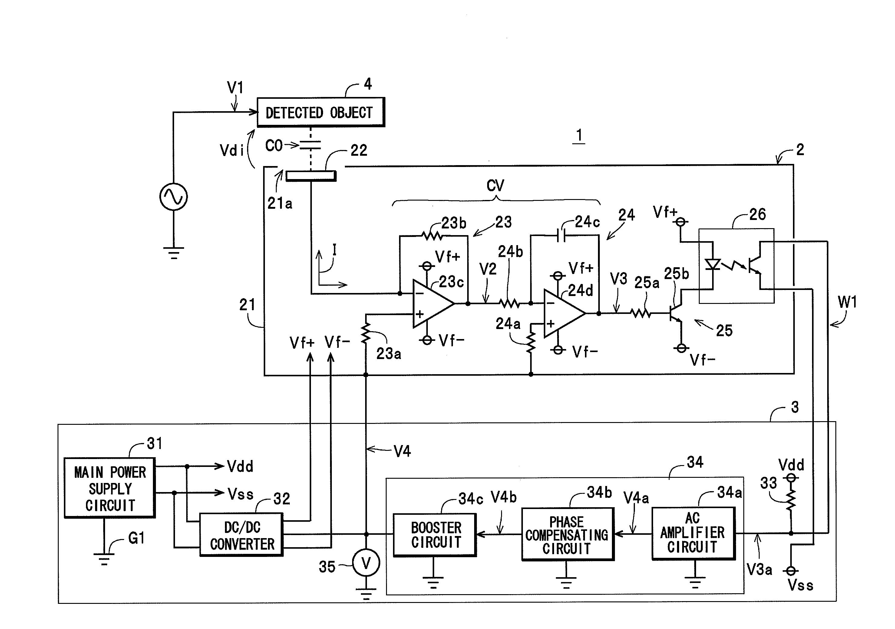
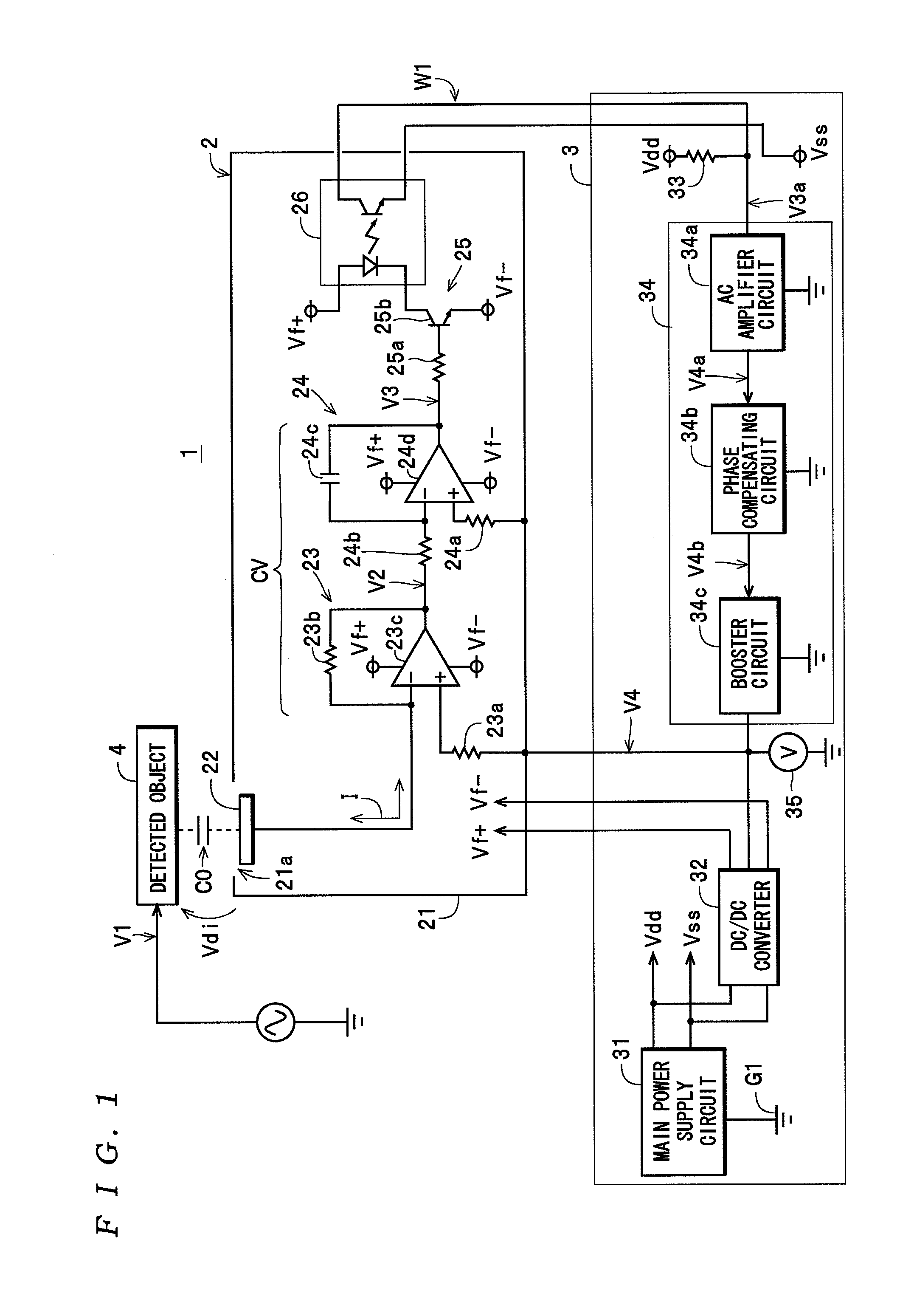
[0088]The voltage detecting apparatus 1 is a non-contact voltage detecting apparatus, includes a floating circuit unit 2 and a main circuit unit 3 as shown in FIG. 1, and is constructed so as to be capable of detecting (measuring) an AC voltage V1 (detected AC voltage) generated in a detected object (measured object) 4 in a non-contact manner.

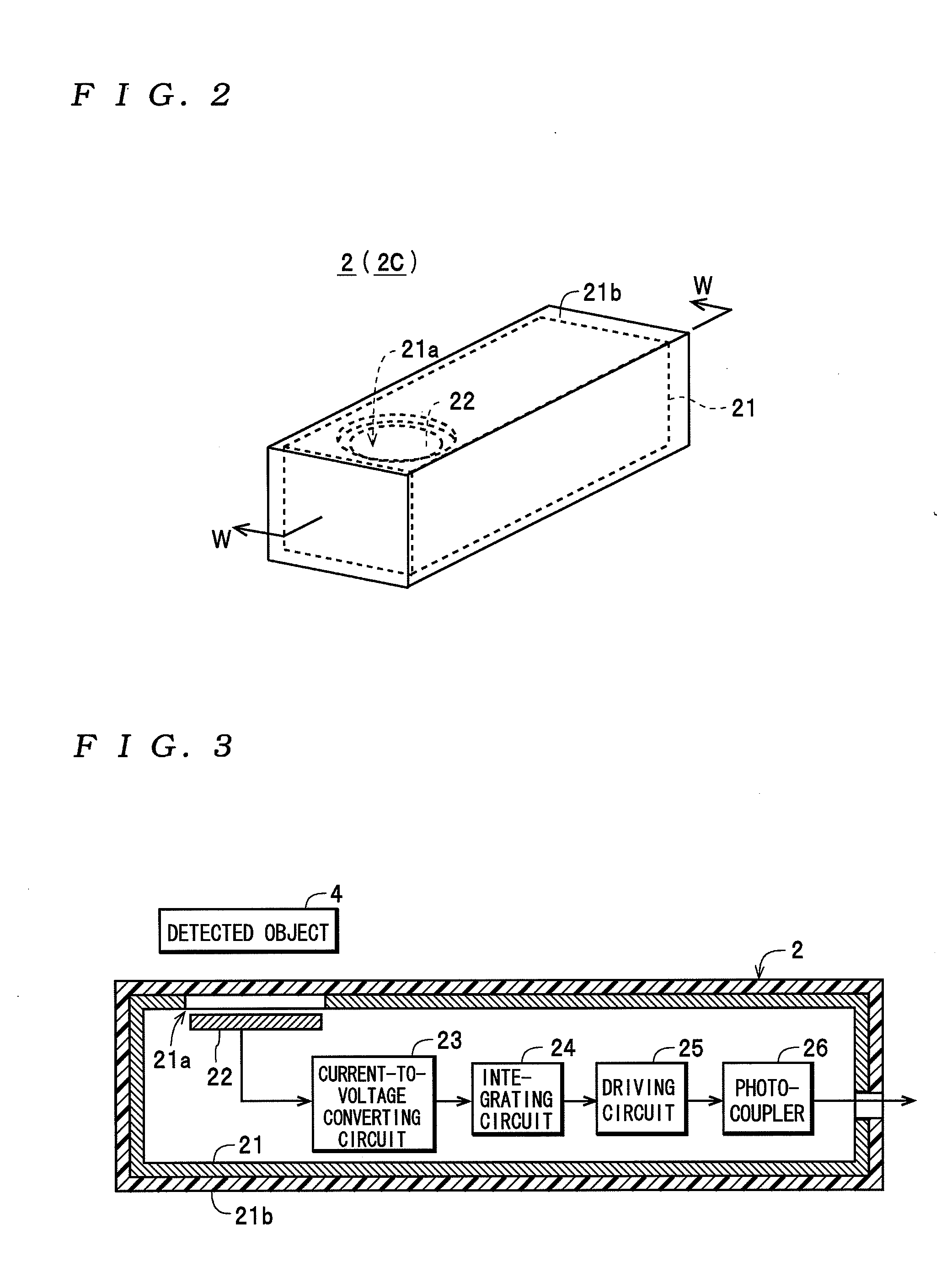
[0089]As shown in FIGS. 1 to 3, the floating circuit unit 2 includes a guard electrode 21, a detection electrode 22, a current-to-voltage converting unit CV, a driving circuit 25, and an insulating circuit 26. As one example in the present embodiment, the current-to-voltage converting unit CV includes a current-to-voltage converting circuit 23 and an integrating circuit 24. Also as one example in the present embodiment, the insulating circuit 26 is constructed of a photocoupler...

second embodiment

[0131]A second embodiment of a voltage detecting apparatus and a line voltage detecting apparatus will now be described with reference to the attached drawings.

[0132]First, a voltage detecting apparatus (second voltage detecting apparatus) 101 according to the present embodiment will be described with reference to the drawings. Note that components that are the same as in the voltage detecting apparatus 1 described above have been assigned the same reference numerals and description thereof is omitted.

[0133]The voltage detecting apparatus 101 is a non-contact voltage detecting apparatus, includes a floating circuit unit 2C and a main circuit unit 3 as shown in FIG. 10, and is constructed so as to be capable of detecting (measuring) an AC voltage V1 (detected AC voltage) generated in a detected object (measured object) 4 in a non-contact manner.

[0134]As shown in FIGS. 10, 11, a floating circuit unit 2C includes the guard electrode 21, the detection electrode 22, a bootstrap circuit 2...

third embodiment

[0159]A third embodiment of a voltage detecting apparatus and a line voltage detecting apparatus will now be described with reference to the attached drawings.

[0160]First, a voltage detecting apparatus (third voltage detecting apparatus) 201 according to the present embodiment will be described with reference to the drawings. Note that components that are the same as in the voltage detecting apparatuses 1, 101 described above have been assigned the same reference numerals and description thereof is omitted.

[0161]The voltage detecting apparatus 201 is a non-contact voltage detecting apparatus and as shown in FIG. 13 includes a floating circuit unit 2D and a main circuit unit 3C. The voltage detecting apparatus 201 is constructed so as to be capable of detecting the AC voltage V1 (detected AC voltage) generated in the detected object 4 using ground potential Vg as a reference.

[0162]As shown in FIG. 13, the floating circuit unit 2D includes a guard electrode 211, a detection electrode ...


PUM


Abstract

A voltage detector that detects an AC voltage in an object includes: an electrode disposed facing the object; a current-to-voltage converter that has a first input set at a reference voltage and a second input connected to the electrode and converts a detection current, which corresponds to a potential difference between the detected AC voltage and the reference voltage on a path including the electrode and a feedback circuit connected to the second input, to a detection signal; an integrating circuit that integrates the detection signal and outputs an integrated signal whose amplitude changes in accordance with the potential difference; an insulating circuit that inputs the detection signal or the integrated signal, and outputs the signal so as to be electrically insulated from the input; and a voltage generating circuit that generates the reference voltage by amplifying a signal based on the integrated signal to reduce the potential difference.

Description

BACKGROUND OF THE INVENTION[0001]1. Field of the Invention[0002]The present invention relates to a voltage detecting apparatus that detects the voltage of a detected object and to a line voltage detecting apparatus equipped with such voltage detecting apparatus.[0003]2. Description of the Related Art[0004]As one example of this type of a voltage detecting apparatus, a non-contact voltage measuring apparatus (hereinafter, also referred to as a “voltage detecting apparatus”) disclosed by Japanese Examined Patent Application Publication H07-58297 is known. This voltage detecting apparatus is a non-contact potential measuring apparatus that reads changes in potential of a detected object (or “sample”) in a non-contact manner, and includes a metal prong with a pointed end, a feedback circuit that detects a field emission current or tunnel current via the metal prong and applies a voltage to the metal prong so as to keep such current constant, and a circuit that reads the voltage of the m...

Claims


Application Information

Patent Timeline
Patent Type & Authority Applications(United States)
IPC IPC(8): G01R19/00G06F19/00
CPCG01R15/16G01R17/06G01R19/0084G01R15/22
Inventor YANAGISAWA, KOICHI
Owner HIOKI DENKI KK
Why Eureka
Try Eureka