
Method and apparatus for measuring viscosity and surface tension

a viscosity and surface tension technology, applied in the direction of flow properties, measuring devices, instruments, etc., can solve the problems of not easy to be automated, not easy to implement in a reproducible daily workflow, and the process is slow and needs large volume samples

Inactive Publication Date: 2009-12-31
FLAMAC
View PDF20 Cites 22 Cited by
  • Summary
  • Abstract
  • Description
  • Claims
  • Application Information

AI Technical Summary

Benefits of technology

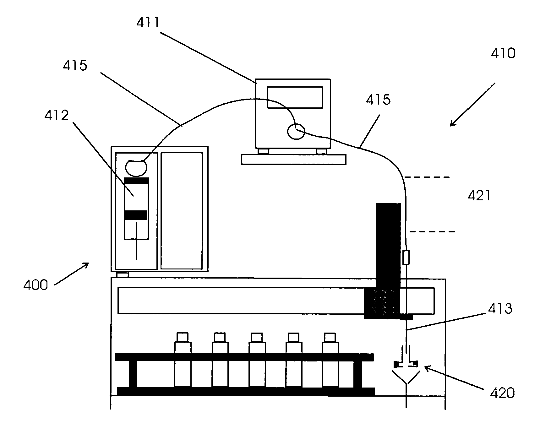
[0016]The use of an image capturing means, and optionally an illumination system, enables the image capturing means and optionally the illumination system to be remotely located from the needle tip where the droplets are formed. Polluting of the image capturing means and optionally the illumination system by droplets e.g. splashing after being separated from the needle tip, may be reduced or even avoided.
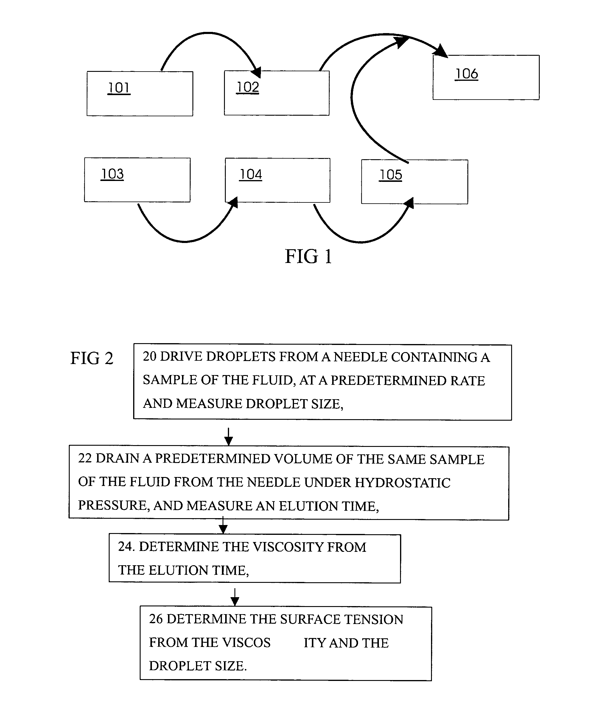
[0018]The method allows or includes determining the viscosity from the elution time, and determining the surface tension from the viscosity and the size-related characteristic of the droplet such as droplet size, volume, diameter, or weight of the test liquid. A better trade off of accuracy and speed of measurement can be made by this method. In particular, the measurement of surface tension being dependent on the viscosity, measurement of both surface tension and viscosity can increase accuracy without adding undue delay. Using the same needle or pipette (i.e. having the same inner diameter) and / or taking liquid from the same sample of test liquid for both measurements can help reduce or avoid systematic errors or contamination errors, and can improve speed of measurement.
[0022]Preferably, the driving fluid, e.g. a driving liquid, has a lower viscosity than the test liquid to be measured. The advantage of this feature is that the viscosity and hence pressure drop caused by the driving fluid, e.g. a driving liquid, can be made low or negligible so that the same needle or pipette may be used for a wide variety of test samples with different viscosities.
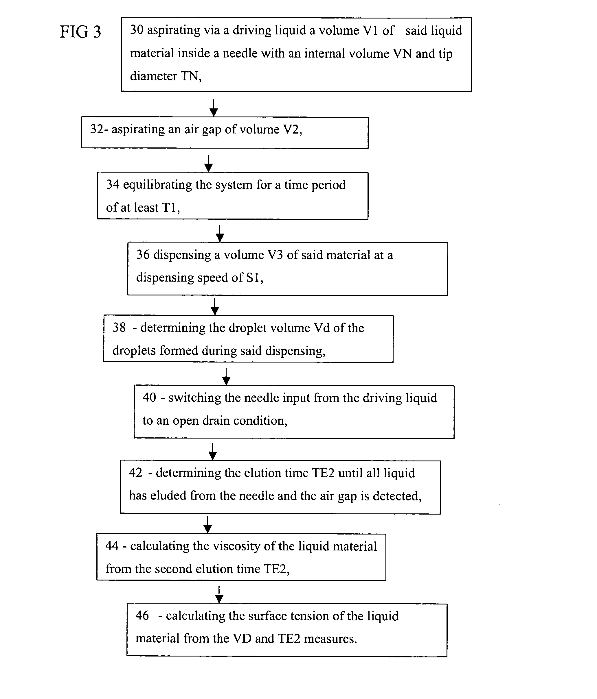
[0024]When the driving fluid is a driving liquid, this driving liquid may be separated from the test liquid via a gas or air gap. After the test liquid has been fully eluted, either the optional air gap or the driving fluid, e.g. the driving liquid, is leaving the needle. In the case of the air gap it is easy to detect this timing since the change in flow with the air passing through the needle is very large. When the driving liquid is leaving the needle, the difference with either the air of the air gap or the test liquid is large, so it is easily determinable.
[0025]Since the test liquid is being eluting out of the needle, the elution speed is preferably kept constant and is preferably only dependent upon the characteristics of the driving liquid and characteristics of the measuring device. As such it can be used as an internal calibration procedure so that any deviation—due to e.g. a faulty sample that was aspirated—is immediately observed and no wrong measurements can be identified. Compared with prior art descriptions the methods to determine viscosity of test liquids such as inks according to the present invention has many benefits: small sample volumes are possible, fast measuring times are possible, automation is easily done, screening of fluids with very largely varying viscosities can be done, auto-cleaning after aspirating bad inks is easily done.
[0037]The volume of test liquid eluted may be a predetermined volume or the apparatus may have a means for in situ measuring of an eluted volume, e.g. eluted with a certain time. The hydrostatic pressure is exerted on the test liquid by the driving fluid such as a driving liquid or driving gas. Preferably, the driving fluid, optionally the driving liquid, has a lower viscosity than the test liquid to be measured. The advantage of this apparatus is that the viscosity and hence pressure drop caused by the driving fluid can be made low or negligible so that the same needle or pipette may be used for a wide variety of test samples with different viscosities.

Problems solved by technology

This is a rather slow process needing large volume samples and different pipettes in function of the measured viscosity range.
For that reason it is not easy to be automated.
Most of these mentioned methods are rather complicated and not easy to implement in a reproducible daily workflow.
The major drawback of this method, however, is that if the viscosity of the test liquid is rather high, the liquid leaves the needle only very slowly or not at all, making it difficult to record viscosity values varying over a wide range.

Method used


Image

  • Method and apparatus for measuring viscosity and surface tension
  • Method and apparatus for measuring viscosity and surface tension
  • Method and apparatus for measuring viscosity and surface tension

Examples


Embodiment Construction

[0053]The present invention will be described with respect to particular embodiments and with reference to certain drawings but the invention is not limited thereto but only by the claims. The drawings described are only schematic and are non-limiting. In the drawings, the size of some of the elements may be exaggerated and not drawn on scale for illustrative purposes. Where the term “comprising” is used in the present description and claims, it does not exclude other elements or steps. Where an indefinite or definite article is used when referring to a singular noun e.g. “a” or “an”, “the”, this includes a plural of that noun unless something else is specifically stated.

[0054]The term “comprising”, used in the claims, should not be interpreted as being restricted to the means listed thereafter; it does not exclude other elements or steps. Thus, the scope of the expression “a device comprising means A and B” should not be limited to devices consisting only of components A and B. It ...


PUM


Abstract

Methods and apparatus for measuring viscosity and / or surface tension of a liquid are described in which droplets are formed at a needle or pipette containing a sample of the test liquid and a size-related characteristic of the droplets such as droplet size, volume, diameter, or weight of the test liquid are measured by means of by capturing an image of the droplets and obtaining the size-related characteristic from the captured image. Subsequently or previously, a volume of the same sample of the test liquid is drained from the needle or pipette under pump pressure or a hydrostatic pressure, and an elution time is measured. The method and apparatus allows or includes determining the viscosity from the elution time, and determining the surface tension from the viscosity and the size-related characteristic of the droplet such as droplet size, volume, diameter, or weight of the test liquid.

Description

[0001]This invention relates to the technical field of methods of measuring at least one rheological property of liquids such as viscosity and / or surface tension, methods of selecting certain liquids such as printing inks based on such methods and apparatus for making such measurements.TECHNICAL BACKGROUND[0002]Viscosity is a measure of the resistance of a fluid to deformation under shear stress, When a force is applied to a volume of material then a displacement (deformation) occurs. If two plates (area, A), separated by fluid distance (separation height, H) apart, are moved (at velocity V by a force F) relative to each other, Newton's law states that the shear stress (the force divided by area parallel to the force, F / A) is proportional to the shear strain rate (V / H). The proportionality constant is known as the (dynamic) viscosity (h).[0003]Viscosity can depend on the shear rate, the temperature, the pressure, the time (history of shear), and the physical and chemical properties ...

Claims


Application Information

Patent Timeline
IPC IPC(8): G01N11/06G01N13/02
CPCG01N11/06G01N2015/1493G01N2013/0241G01N13/02
Inventor DESIE, GUIDOVAN GEEL, ERIKVAN GEMERT, DANNYDIELTJENS, GUNTERVAN DEN BOSSCHE, KARL
Owner FLAMAC
Learn More