Optimal Battery Current Waveform for Bidirectional PHEV Battery Charger

a technology of phev battery charger and current waveform, which is applied in the direction of electric power, electric vehicles, transportation and packaging, etc., can solve the problems of increasing device voltage stress, short lifetime of electrolytic capacitor or high volume of film capacitor, and pulsating input power at double line frequency, etc., to achieve long lifetime power converter, high efficiency, and high density

Active Publication Date: 2016-06-16
VIRGINIA TECH INTPROP INC
View PDF4 Cites 18 Cited by
  • Summary
  • Abstract
  • Description
  • Claims
  • Application Information

AI Technical Summary

Benefits of technology

[0008]In one embodiment, the present invention concerns a high density, high efficiency and long lifetime power converter, which may interface with a single-phase AC voltage connected to an energy storage device. This converter may be either unidirectional or bidirectional. In the power converter, the charging or discharging current of t

Problems solved by technology

Single phase AC/DC converter with power factor correction has an issue of pulsating input power at double line frequency.
The required capacitance, depending on the ripple power at double line frequency, will result in either a short lifetime with electrolytic capacitors or high volume with film capacitors.
This concept can be implemented directly to the DC link capacitor, as shown in a grid-interface bi-directional converter, which increases device voltage stress and the capacitance reduction is limited due to the range limitation of DC link voltage swing.
Alternatively,

Method used


Image

  • Optimal Battery Current Waveform for Bidirectional PHEV Battery Charger
  • Optimal Battery Current Waveform for Bidirectional PHEV Battery Charger
  • Optimal Battery Current Waveform for Bidirectional PHEV Battery Charger

Examples


Embodiment Construction

[0031]Detailed embodiments of the present invention are disclosed herein; however, it is to be understood that the disclosed embodiments are merely exemplary of the invention, which may be embodied in various forms. Therefore, specific structural and functional details disclosed herein are not to be interpreted as limiting, but merely as a representative basis for teaching one skilled in the art to variously employ the present invention in virtually any appropriately detailed method, structure or system. Further, the terms and phrases used herein are not intended to be limiting, but rather to provide an understandable description of the invention

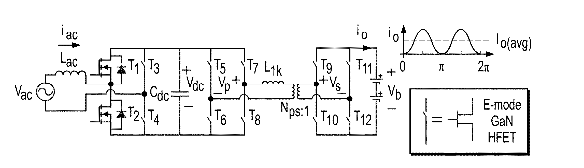
[0032]The present invention, for exemplary purposes, provides an analysis uses the charging power flow as an example but the present invention also applies to power flow from energy storage to the AC side.

[0033]A single phase rectifier in a PHEV battery charger requires substantial unity power in the factor at the input. Therefore, in normal...


PUM


Abstract

The present invention provides a battery charger and battery charging method controlled with a charging waveform input of an AC-DC switching circuit to a DC link and a DC-DC stage converter for outputting a regulated DC voltage. The method determining the charging waveform comprising the steps of selecting a Pulse Width Modulation (PWM) zero-off charging waveform signal input to the AC-DC switching circuit and calculating a ripple power at the DC link based on the signal input power and output power of the regulated DC voltage output.

Description

RELATED APPLICATIONS[0001]This application claims the benefit of U.S. Provisional Application No. 62 / 092,324 filed on Dec. 16, 2014 and herein incorporated by reference.STATEMENT REGARDING FEDERALLY SPONSORED RESEARCH & DEVELOPMENT[0002]Not applicable.INCORPORATION BY REFERENCE OF MATERIAL SUBMITTED ON A COMPACT DISC[0003]Not applicable.BACKGROUND OF THE INVENTION[0004]Single phase AC / DC converter with power factor correction has an issue of pulsating input power at double line frequency. This pulsating power usually is stored in an intermediate capacitor if output power is DC. The required capacitance, depending on the ripple power at double line frequency, will result in either a short lifetime with electrolytic capacitors or high volume with film capacitors. Especially when wide bandgap semiconductors have been used to shrink other passive components significantly, the DC link capacitor becomes one major power density barrier.[0005]In some applications, such as automobile and avi...

Claims


Application Information

Patent Timeline
IPC IPC(8): H02J7/00
CPCH02J7/0052H02J7/007H02M7/797H02J7/02H02J2207/20H02J7/00
Inventor XUE, LINGXIAOMATTAVELLI, PAOLOBOROYEVICH, DUSHAN
Owner VIRGINIA TECH INTPROP INC
Why Eureka
Try Eureka