Driving of multi-channel speakers

a multi-channel speaker and driver technology, applied in the direction of transducer protection circuits, stereophonic arrangments, electrical apparatus, etc., can solve the problems of degraded spatial perception, reduced perceived quality, and blurry sound stage, so as to improve spatial perception, reduce driver excursion, and improve the effect of bass frequency extension

Inactive Publication Date: 2012-02-09
MMD HONG KONG HLDG LTD
View PDF2 Cites 15 Cited by
  • Summary
  • Abstract
  • Description
  • Claims
  • Application Information

AI Technical Summary

Benefits of technology

[0019]This may provide particularly advantageous performance in many embodiments. For example, the frequencies at which the low frequency bass boost is applied may be dynamically varied. In some embodiments, the lower frequency for a frequency band in which the low frequency boost is applied may be adjusted in dependence on the driver excursion indication.
[0020]In accordance with an optional feature of the invention, the adjustment means is arranged to bias the cross-over frequency and a lower frequency for the low frequency boost towards lower frequencies for a reduced driver excursion.
[0021]This may provide particularly advantageous performance. Specifically, the invention may allow the bass frequency extension to be extended to lower frequencies for lower sound levels, thereby allowing the second audio driver to reproduce a larger part of the sound image, resulting in e.g. an improved spatial perception and a more defined sound stage. However, at higher sound levels, the bass frequency extension may be reduced thereby reducing the risk of distortion or damage caused by excessive driver excursions.

Problems solved by technology

However, at these frequencies the radiated sound will be perceived to have some directional cues and the high cross-over frequency may thus reduce the perceived quality and may in particular result in degraded spatial perception.
Indeed, typically the sound stage tends to become blurry, and attenuated voices may be perceived to originate partially from the subwoofer rather than the desired spatial position.

Method used


Image

  • Driving of multi-channel speakers
  • Driving of multi-channel speakers
  • Driving of multi-channel speakers

Examples


Embodiment Construction

[0048]The following description focuses on embodiments of the invention applicable to a multi-channel surround sound audio system. However, it will be appreciated that the invention is not limited to this application but may be applied to many other sound systems.

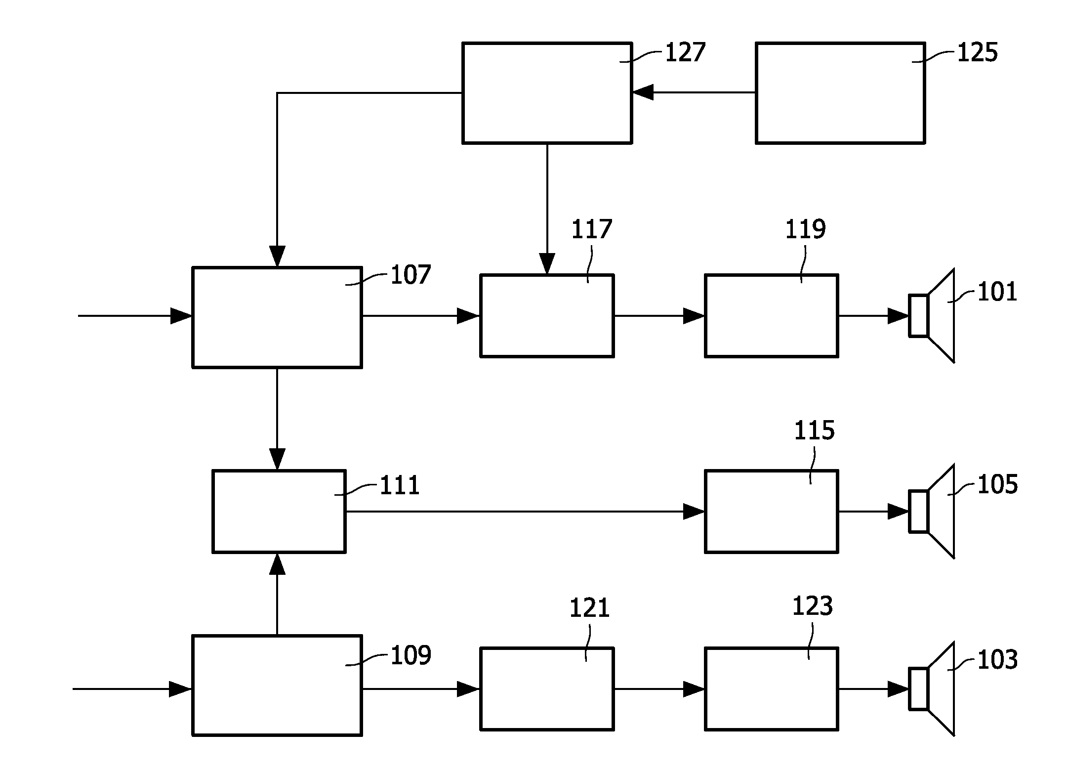
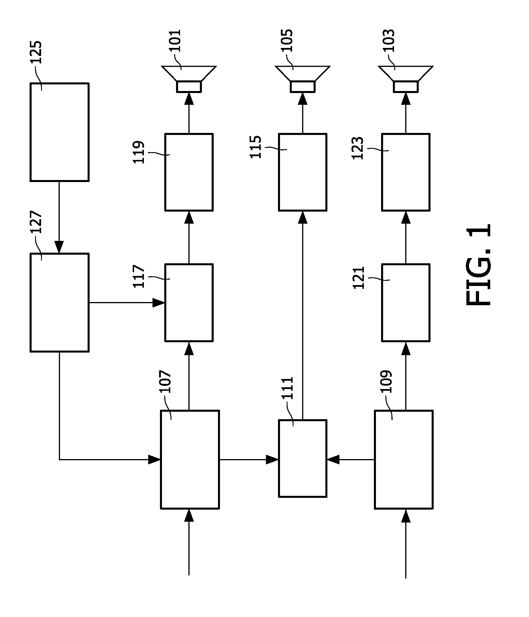
[0049]FIG. 1 illustrates an example of an audio system in accordance with some embodiments of the invention. The audio system comprises a drive system for driving a plurality of audio drivers (such as loudspeakers). The drive system may specifically be a multi-channel audio amplifier.

[0050]In the example, the audio system is a home cinema system providing surround sound through the use of a discrete satellite loudspeaker for each spatial channel and a subwoofer which is common for the plurality of the spatial channels.

[0051]Thus, FIG. 1 illustrates a plurality of audio drivers 101, 103 which each radiate sound for one spatial channel. The audio drivers 101, 103 are specifically satellite loudspeakers which are relatively sm...


PUM


Abstract

A drive system comprises a splitter (107) which generates a low frequency signal and high frequency signal from an input signal. A first drive circuit (111, 115) is coupled to the splitter (117) and generates a drive signal for an audio driver (105) from the low frequency signal. A second drive circuit (117, 119) is coupled to the splitter (117) and generates a drive signal for a second audio driver (101) from the high frequency signal. The second drive circuit (117, 119) provides a bass frequency extension for the second audio driver (101) by applying low frequency boost to the low frequency signal. A processor (125) determines a driver excursion indication for the second audio driver (101) and a controller (127) performs a combined adjustment of a cross-over frequency for the high and low frequency signals and a characteristic of the low frequency boost based on the driver excursion indication. The invention may provide improved interworking between e.g. a subwoofer and satellite speakers.

Description

FIELD OF THE INVENTION[0001]The invention relates to driving of multi-channel speakers and in particular, but not exclusively, to driving of speakers in a home cinema sound system.BACKGROUND OF THE INVENTION[0002]Sound reproduction using more than two channels for providing an enhanced spatial experience has become very popular. For example, home cinema sound systems employing five or seven different spatial channels have become very popular. However, in order to reduce the impact of having to provide such a high number of sound sources, most home cinema sound systems use relatively small satellite loudspeakers for mid and high frequency reproduction combined with a subwoofer for low frequency reproduction. Such an arrangement exploits the fact that human perception predominantly takes the spatial direction cues from mid to high frequencies whereas the spatial cues from low frequency audio are often relatively insignificant.[0003]The frequency that indicates the differentiation betw...

Claims


Application Information

Patent Timeline
Patent Type & Authority Applications(United States)
IPC IPC(8): H04R5/00
CPCH04R3/007H04R29/001H04R3/14H04R3/04
Inventor DE POORTERE, GERRIT
Owner MMD HONG KONG HLDG LTD
Why Eureka
Try Eureka