
Marine folding tower

a technology of folding towers and folding plates, which is applied in the field of folding plates, can solve the problems of operator injury and damage to the vessel, and achieve the effects of less manual effort, convenient and stable transport of the vessel, and convenient downward movemen

Inactive Publication Date: 2009-12-31
BLUMBERG RYAN
View PDF6 Cites 19 Cited by
  • Summary
  • Abstract
  • Description
  • Claims
  • Application Information

AI Technical Summary

Benefits of technology

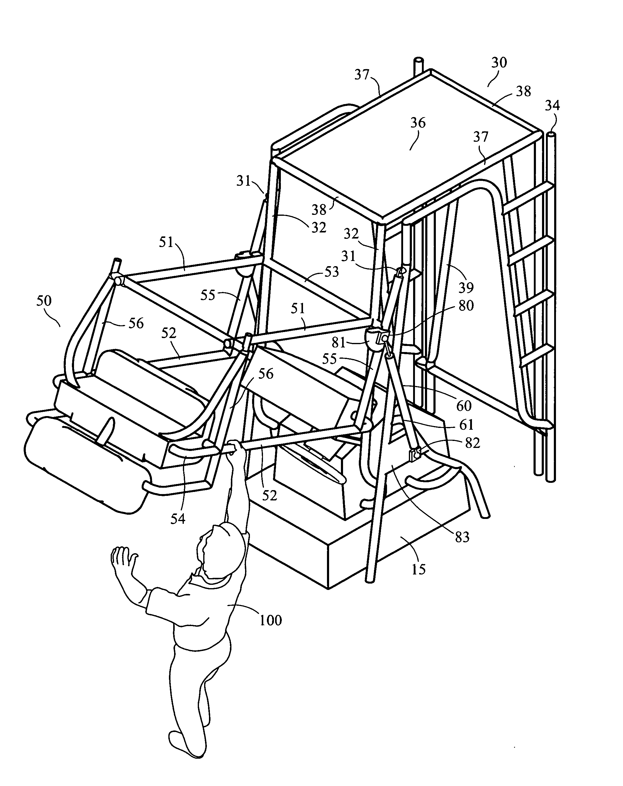
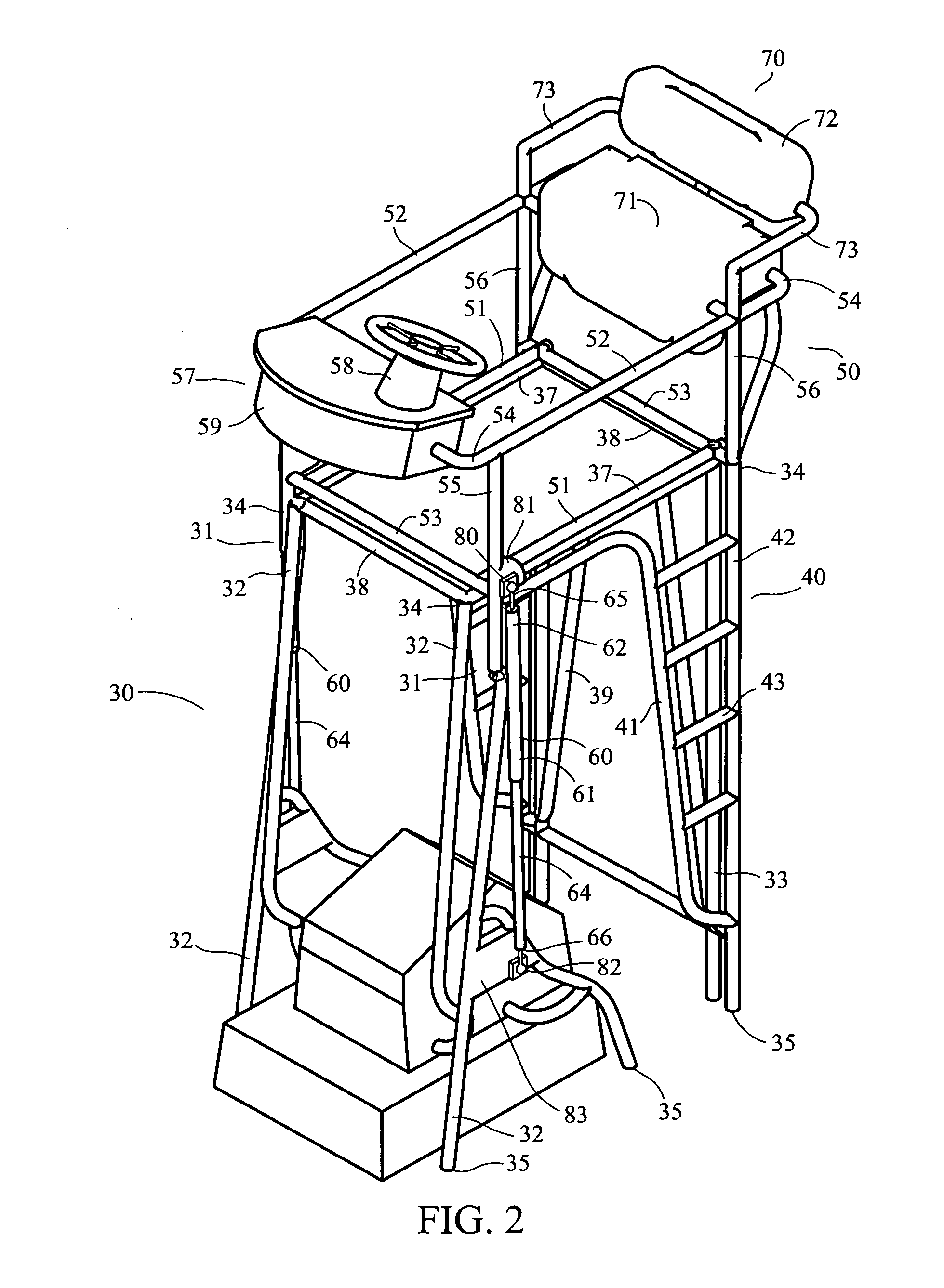
[0016]This invention comprises a folding marine tower apparatus attachable atop and extending upward from the deck structure of a vessel, including one or more gas spring or hydraulic or electric rams or shock absorbers attached to the upper and lower frame assemblies of the folding tower or station. By attaching one end of the gas spring or shock absorber to the upper frame assembly and the other end to the lower frame assembly, the folding action requires substantially less manual effort. The gas spring / shock absorbers may be of different lengths, diameters, and materials, and may operate by electric, gas, hydraulic, air, or other function. The present invention provides an improved alternative by providing a folding boat tower which, by the utilization of pressurized fluid, preferably pressurized air, facilitates the downward movement of the upper frame assembly into a lowered position to allow clear passage of the vessel under bridges and other objects and easier and more stable transport of the vessel on trailers with less wind drag and noise, and further facilitates the upward movement required to return the upper frame assembly to the upright, operating position above the lower frame assembly.
[0017]The purpose of this invention is to provide a convenient means for temporarily reducing the height clearance of a vessel equipped with the folding marine tower apparatus which has the following characteristics: ease of use; safe, convenient, and quick operation of a heavy folding boat tower with minimal physical effort by only one person having limited technical skill and knowledge; simple, low-cost construction, with few parts; ease of installation on new vessels; ease of retrofitting existing vessels; and low maintenance and high energy efficiency, resulting from a simple, durable construction having few parts none of which are motorized.

Problems solved by technology

Otherwise, the kinetic energy caused by the mass in motion can result in damage to the vessel and injury to the operator.

Method used


Image

  • Marine folding tower
  • Marine folding tower
  • Marine folding tower

Examples


Embodiment Construction

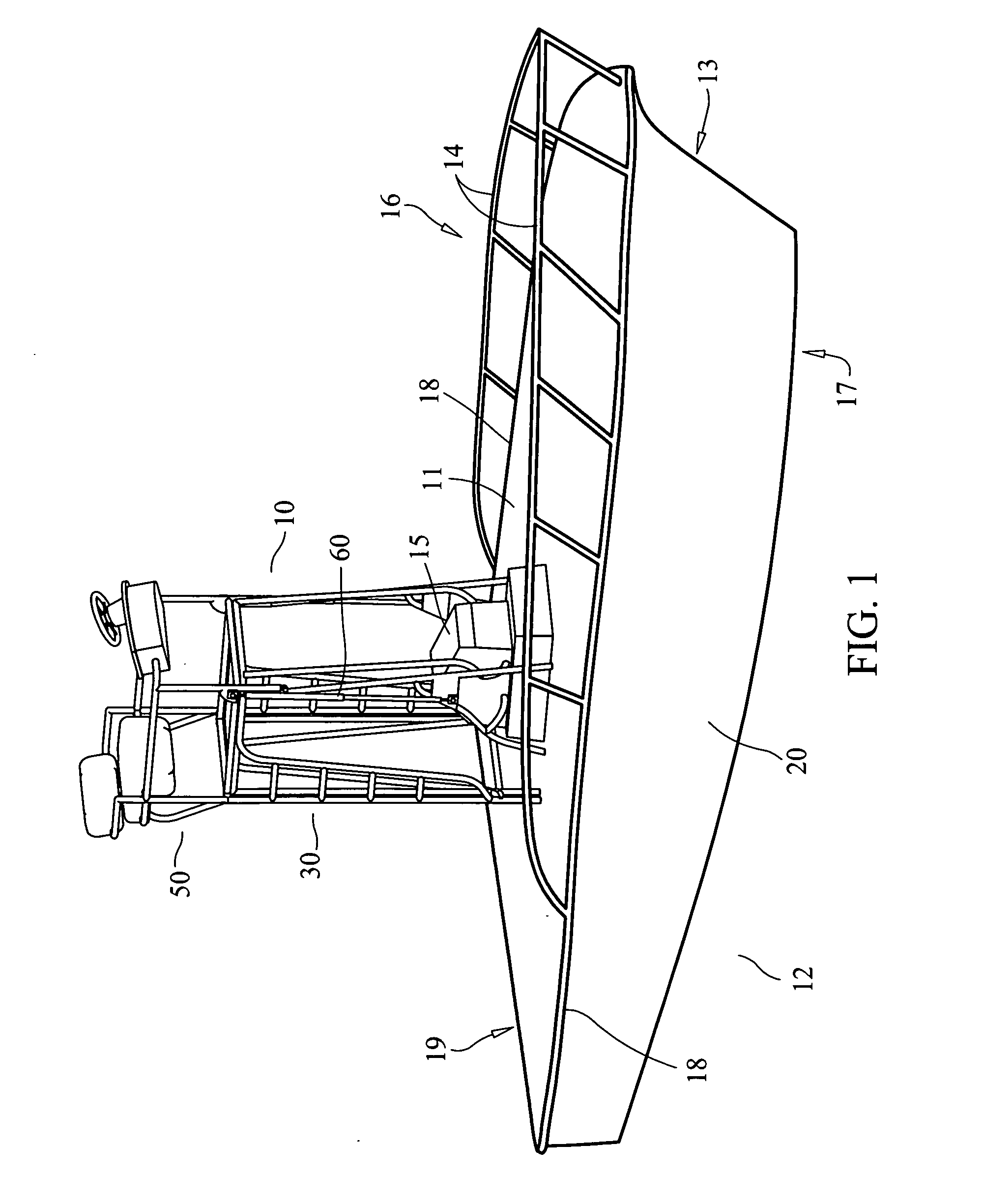
[0028]With reference to the drawings, like reference numerals designate like or similar parts throughout the various views. FIG. 1 illustrates the marine folding tower 10 of the present invention mounted on the deck 11 of a boat 12. The boat has a bow or forward area 13, bow rails 14, center console 15, port side 16, starboard side 17, gunwhales 18 on each side, a stern or aft area 19, and a hull 20.

[0029]The tower is comprised of two sections or frame assemblies, a lower frame assembly 30, which is fixed in a stationary position to the boat's deck, and an upper frame assembly 50, which is rotatable from an upright position as shown in FIGS. 1, 2, 3, 6 and 7 to a downward or folded position around pivot points 31 on the port side and starboard sides of the lower frame assembly 30 as shown in FIGS. 2, 3, 4, 5 and 7.

[0030]The tower's lower frame assembly 30 typically includes a plurality of spaced apart forward support legs 32 and aft support legs 33 having upper ends 34 and lower end...


PUM


Abstract

A system that will result in less physical effort in the lowering or raising of a marine folding tower, spotting station, driving station, fishing tower, or tuna tower. The system will be installed on a fishing boat, pleasure boat, or other marine vessel. The system comprises at least one gas spring, or hydraulic or electric ram or shock absorber of any size or style that attaches to both the upper frame assembly and lower frame assembly of the tower or other station.

Description

[0001]The present invention relates to marine folding towers mounted over the deck area of recreational, pleasure, and fishing boats.CROSS-REFERENCE TO RELATED APPLICATIONS[0002]Not Applicable.STATEMENT REGARDING FEDERAL RESEARCH[0003]There are no rights to this invention under federally sponsored research and development.BACKGROUND OF THE INVENTION[0004]Various types of towers generally referred to as “boat towers”, “tuna towers”, or “fishing towers” are in common use on recreational, pleasure, and fishing boats. Such towers form a structure over part of the deck surface of the boat to provide an elevated piloting or control station, a spotting station, a location for mounting electronic equipment, shelter from the elements, and shade from the sun.[0005]These marine tower structures must be lowered to pass beneath limited clearance bridges and other objects, to permit safe transport on vehicles, and to facilitate storage. Folding boat towers which pivot in a forward and downward di...

Claims


Application Information

Patent Timeline
IPC IPC(8): B63B17/00
CPCB63B17/00
Inventor BLUMBERG, RYAN
Owner BLUMBERG RYAN
Learn More