Device and method for the manufacture of elements in composite material

a composite material and element technology, applied in the direction of manufacturing tools, efficient propulsion technologies, other domestic articles, etc., can solve the problems of excessive complexity of the application of the pultrusion process for the production of stringers and stiffeners, and the limited automaticity of manufacturing processes

Inactive Publication Date: 2009-12-31
AIRBUS OPERATIONS SL
View PDF2 Cites 18 Cited by
  • Summary
  • Abstract
  • Description
  • Claims
  • Application Information

AI Technical Summary

Benefits of technology

[0010]The method according to the invention permits the taping and cutting of the laminates without polymerization that will give rise to the stringers and stiffeners, with all their complexity, placing these laminates in moulds that will serve as support for the forming operation (which can be the curing moulds of the stringers or stiffeners), comprising the use of a train of movable rollers for compacting and forming the laminates of the stringers or stiffeners against said moulds.

Problems solved by technology

However, the automation of manufacturing processes has been limited almost exclusively to the production of large two-dimensional laminates (skins of large aerofoils such as wings, stabilizers or fuselage skins), whereas the manufacture and integration of reinforcing elements and stiffeners proper of the monolithic configurations of these aeronautical structures (stringers and stiffeners) still include a considerable ratio of manual manufacturing.
However, application of the pultrusion process is excessively complex for the production of stringers and stiffeners with the configurations usually employed in aeronautical structures: laminates of large thickness, with variable thicknesses, considerable curvature, with changes of plane necessary for connecting them to skins of variable thickness, etc.

Method used


Image

  • Device and method for the manufacture of elements in composite material
  • Device and method for the manufacture of elements in composite material
  • Device and method for the manufacture of elements in composite material

Examples


first embodiment

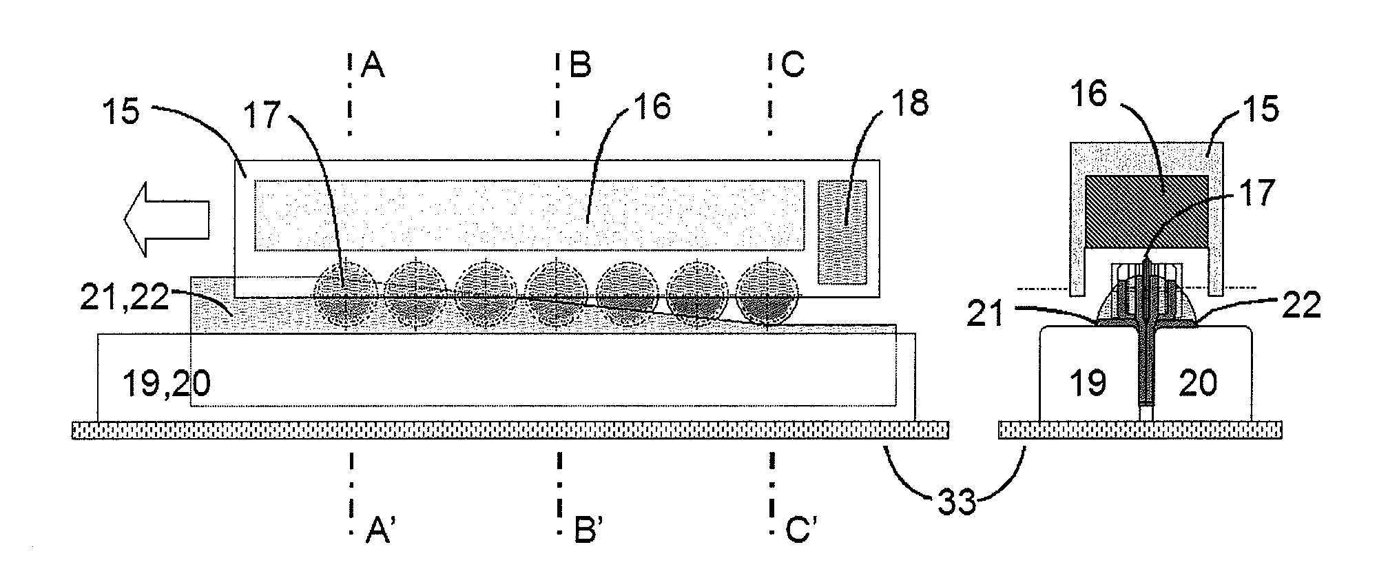
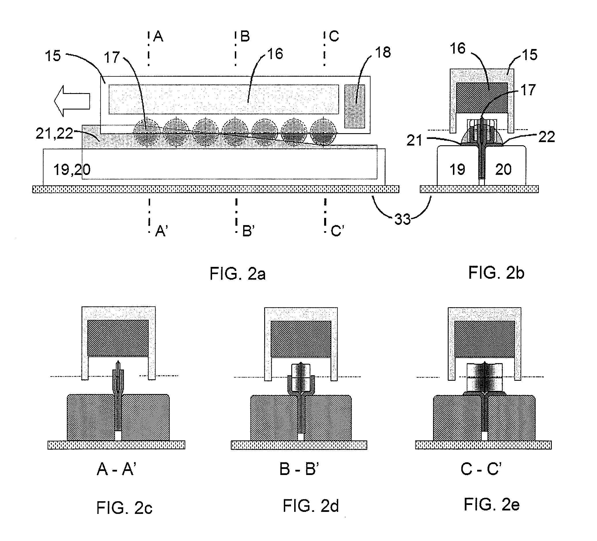
[0027]FIGS. 2a and 2b show, schematically, the device for the manufacture of structures of composite according to the present invention, comprising a movable head 15 that can travel longitudinally along a fixed bedplate formed by a support 33 on which two forming modules 19, 20 rest, which lock together two flat laminates 21, 22 in the vertical position. The movable head 15 basically comprises a heating system 16 for heating a roller train 17 and the two laminates21, 22 that are to be formed, as well as a cooling system 18 based on injection of cold air or gas, or on any other equivalent system that permits the laminates 21, 22 to be cooled once formed. Moreover, FIGS. 2c, 2d and 2e show three sections A-A′, B-B′ and C-C′ of FIG. 2a that show three consecutive states of forming of the laminates 21, 22.

[0028]As shown schematically in FIGS. 3a-3c, the operations of the forming process of the laminates 21, 22 according to a first embodiment of the invention can be divided into three st...

third embodiment

[0036]As can be seen from FIG. 7, according to the invention, the forming of a different stringer section is possible, in which in addition to the flat laminates 21, 22, a third laminate 23 is introduced, which will be inserted between the aforementioned laminates 21, 22, and will form part of the web of the stringer. The roller train 17 that performs the progressive forming of the laminates of the new section described in FIG. 7, comprises a spacing 25 between the two halves of the rollers, of width equal to the width of the intermediate laminate 23, for adapting the process to the new section required for the stringer.

[0037]Finally, FIG. 9 shows schematically, in section, the forming and curing angles 24, according to a third embodiment of the invention, already closed. FIG. 9 also shows the laminates 21, 22 and 23 in successive stages of the forming process of the new stringer section with a central laminate 23 in its web.


PUM

PropertyMeasurementUnit
widthaaaaaaaaaa
thicknessaaaaaaaaaa
mechanical propertiesaaaaaaaaaa

Abstract

The invention relates to a device for the manufacture of three-dimensional beam type elements in composite material with reinforcing fibres preimpregnated with polymeric resins, starting with laminates (21, 22) layed and precut without polymerization, said device comprising a head (15) that comprises in its turn a roller train (17), it being possible for said head (15) to move longitudinally along a fixed bedplate, in such a way that, as said head (15) moves, the roller train acts on the laminates (21, 22) without polymerization, compacting and forming them, thus forming the laminates (21, 22) with their final geometry in one go, in such a way that said laminates (21, 22) are ready for their subsequent integration. The invention also relates to a method of manufacture of three-dimensional beam type elements in composite material.

Description

FIELD OF THE INVENTION[0001]The present invention relates to a device for the manufacture of elements in composites, in particular for aircraft, as well as to a method of manufacture of said elements in composites.BACKGROUND OF THE INVENTION[0002]The intensive introduction of advanced composites in aerospace primary structures has become a fundamental method of structural optimization, based on the weight saving and improvement of mechanical properties, thus becoming one of the primary objectives in the design and manufacture of the new generations of aircrafts.[0003]This intensive introduction of composites has been possible owing to improvements in techniques and equipment for automatic stacking and cutting of laminates obtained from plies constituted of reinforcing fibres pre-impregnated with polymeric resins. However, the automation of manufacturing processes has been limited almost exclusively to the production of large two-dimensional laminates (skins of large aerofoils such a...

Claims


Application Information

Patent Timeline
Patent Type & Authority Applications(United States)
IPC IPC(8): B28B3/12B28B5/00B29C53/54B29D99/00
CPCB29C33/02Y10T156/101B29C35/16B29C43/06B29C43/3642B29C43/3697B29C43/46B29C43/52B29C70/345B29C2043/3644B29C2043/3647B29D99/0003B29K2105/246B29L2031/003Y02T50/433B29C35/02Y02T50/40B29C70/541B28B3/12
Inventor MENENDEZ MARTIN, JOSE MANUELPEREZ PASTOR, AUGUSTOMIGUES CHARINES, YOLANDA
Owner AIRBUS OPERATIONS SL
Why Eureka
Try Eureka