Telecom shelter cooling and control system

a control system and telecom shelter technology, applied in vehicle heating/cooling devices, process and machine control, air heaters, etc., can solve the problems of not being practical, not being able to operate for a long time, and being relatively short, so as to accelerate the exhaustion of the shelter and reduce the energy use and operation costs of the telecom shelter.

Active Publication Date: 2009-12-31
SCHROFF TECH INT
View PDF11 Cites 33 Cited by
  • Summary
  • Abstract
  • Description
  • Claims
  • Application Information

AI Technical Summary

Benefits of technology

[0013]Many benefits are achieved by way of the present invention over conventional techniques. For example, embodiments of the present invention provide an alternate cooling system in place of conventional air conditioning system, which can be used for cooling outdoor shelter housing electrical equipment in the events where standard AC power is interrupted or failed. Certain embodiments of the present invention significantly reduces energy use and operation costs of the telecommunication shelter. Some embodiments further provide sustained operation of the communication electronics within the shelter in the event of a power failure during hurricane or earthquake. Under updated field application requirement for 4-8 hours after loss of power, the exiting telecom shelter can be kept for using with minimum amount of modification and installation of the direct

Problems solved by technology

Thus, the time that the telecom systems can operate is not limited by the battery life, but is limited by the time that the system can operate before it reaches the over-temperature shutdown threshold when the A/C system for providing cooling to the shelter is no longer functioning.
This time depends on the external ambient conditions but is typically quite short ( approx 20 minutes to 1 hour) for conventional telecom shelter.
However

Method used


Image

  • Telecom shelter cooling and control system
  • Telecom shelter cooling and control system
  • Telecom shelter cooling and control system

Examples


Embodiment Construction

[0022]The present invention relates generally to system cooling techniques. In particular, embodiments of the present invention provide a method and system for providing an alternate cooling to an outdoor shelter housing electrical equipment. Merely by way of example, the invention has been applied to a telecommunication shelter, but it would be recognized that the invention has a much broader range of applicability.

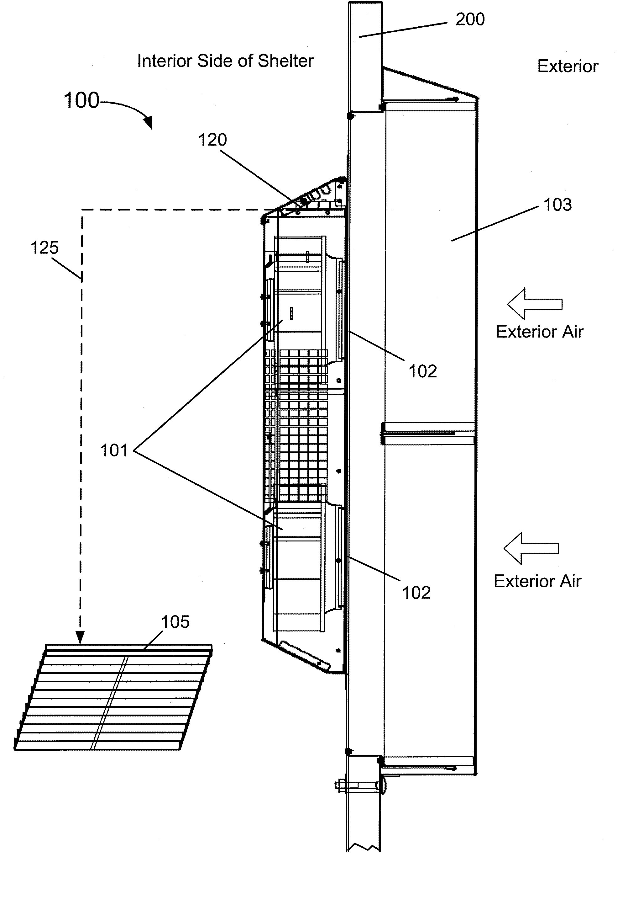
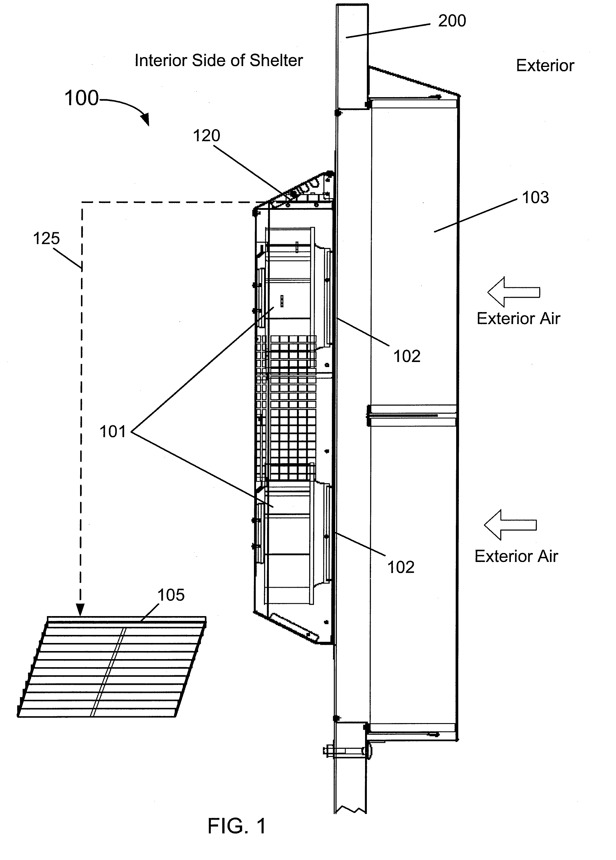
[0023]FIG. 1 is a schematic diagram showing a side view of a cooling system according to an embodiment of the present invention. This diagram is merely an illustration and should not limit the scope of the claims herein. One of skilled in the art should recognize many alternatives, variations, and modifications. As shown in one implementation, a direct air cooling system 100 is structured to be mounted on a position of a shelter door 200 (side view is shown). At least partially, the direct air cooling system 100, or simply called the cooling system, includes one or more ...


PUM


Abstract

A system configured to provide cooling of electronic equipment in a shelter in combination with an air conditioning (A/C) system. The system includes one or more blowers for drawing air into the shelter, a damper arrangement for controlling air exhaust. The system further includes a DC powered controller coupled to the one or more blowers, the damper arrangement, and the A/C system. The controller is configured to receive at least a first analog input signal associated with a shelter-interior temperature, a second analog input signal associated with a shelter-exterior temperature, and a plurality of alarm input signals and to generate the one or more first control signals to control blower rotational speed, the second control signal to open/close the damper arrangement, and a third control signal to inhibit/activate the A/C system based on at least the first analog input signal, or the second analog input signal, or a plurality of alarm input signals, or a combination of these.

Description

BACKGROUND OF THE INVENTION[0001]The present invention relates generally to system cooling techniques. In particular, embodiments of the present invention provide a method and system for providing an alternate cooling to an outdoor shelter housing electrical equipment. Merely by way of example, the invention has been applied to telecommunications shelters, but it would be recognized that the invention has a much broader range of applicability.[0002]Telecommunication (telecom) shelters are typically constructed as an outdoor facility in either steel or pre-cast concrete structure for housing an electrical system. Physical dimensions for such shelters are about 20 ft in length, 10 ft in width, 10 ft in height with an access door and several access hatches for cable access. These shelters are usually attached to split system air-conditioning units for providing cooling for the electrical system therein. A conventional air conditioning (A / C) system associated with the shelter is typical...

Claims


Application Information

Patent Timeline
IPC IPC(8): B60H1/00F28F13/12G05B15/00
CPCE04H1/1238H05K7/207F24F11/0001
Inventor THERRIEN, DAVIDRIDDOCH, HENRY
Owner SCHROFF TECH INT
Why Eureka
Try Eureka