Engine generator

a technology of engine generator and engine, which is applied in the direction of shock absorbers, locomotive transmissions, electric motor propulsion transmissions, etc., can solve the problems of increased weight of engine generator, reduced transportability of engine generator, and increased vibration of engine/generator units, so as to reduce the vertical component of engine/generator units vibration, the effect of reducing the vibration of the engine/generator units and increasing the vibration amoun

Active Publication Date: 2009-12-31
HONDA MOTOR CO LTD
View PDF10 Cites 8 Cited by
  • Summary
  • Abstract
  • Description
  • Claims
  • Application Information

AI Technical Summary

Benefits of technology

[0018]The bottom bump stopper is preferably caused to make contact in the vicinity of the external periphery of the bottom section of the engine / generator unit in order to reduce the vertical component of the vibrations of the engine / generator unit. On the other hand, the vicinity of the external periphery of the bottom section is a location set relatively away from the center of gravity position of the engine / generator unit, and is it possible that the amount of vibration will be increased. However, the vibrations of the engine / generator unit are reduced by the center bump stopper of claim 1. Accordingly, the amount of vibration can be reduced in the location that makes contact with the bottom bump stopper. The vibrations in the contact location can thereby be sufficiently reduced even when the bottom bump stopper is made more compact.

Problems solved by technology

However, since the weight is increased when the engine generator is relatively large, it is difficult to use the resin case to support the upper end sections of the pair of reinforcement frames that are an inverted U-shape in cross section.
However, the weight of the engine generator is increased and the transportability of the engine generator is compromised when the resin case is replaced with a steel case.

Method used


Image

  • Engine generator
  • Engine generator
  • Engine generator

Examples


Embodiment Construction

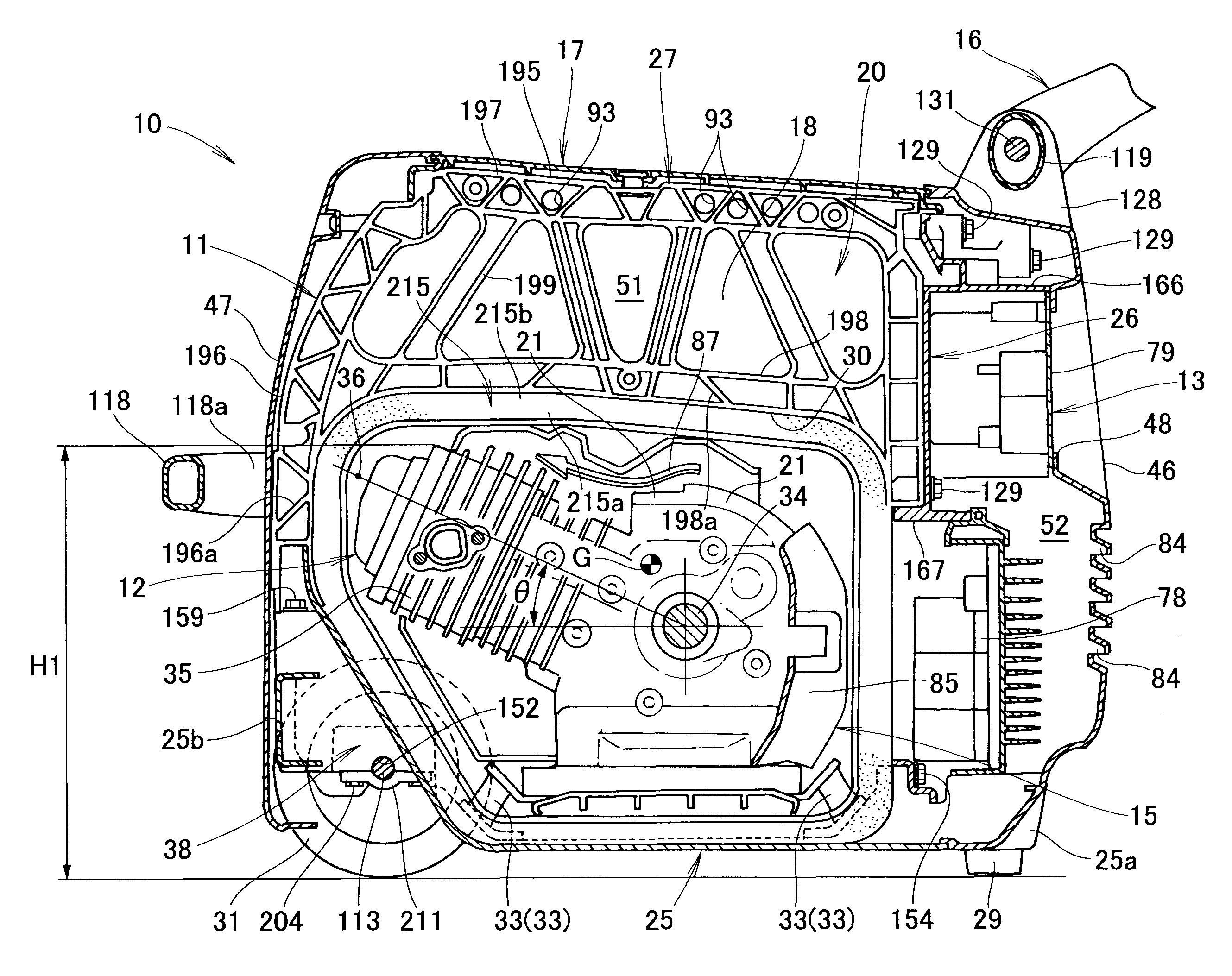
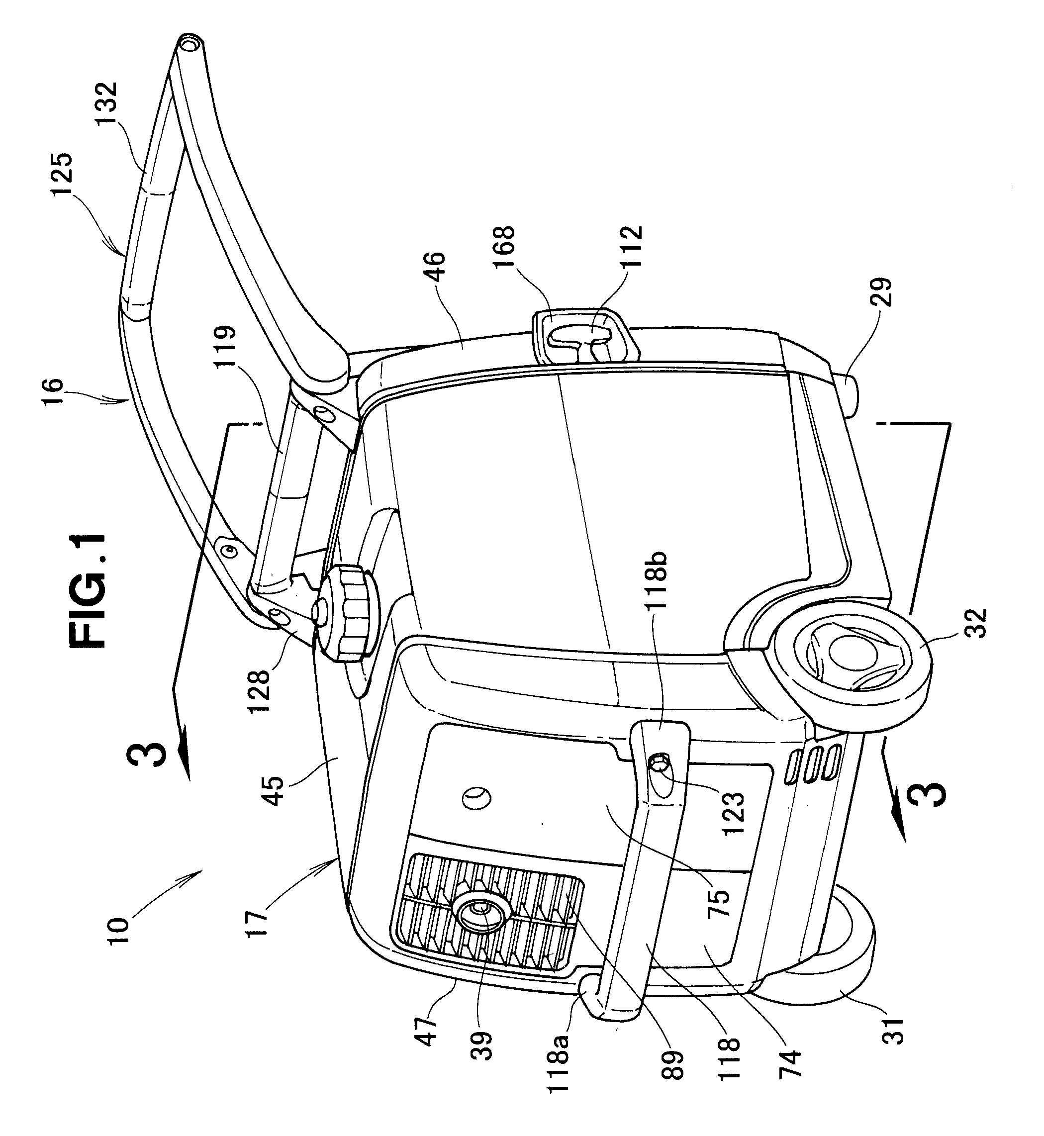
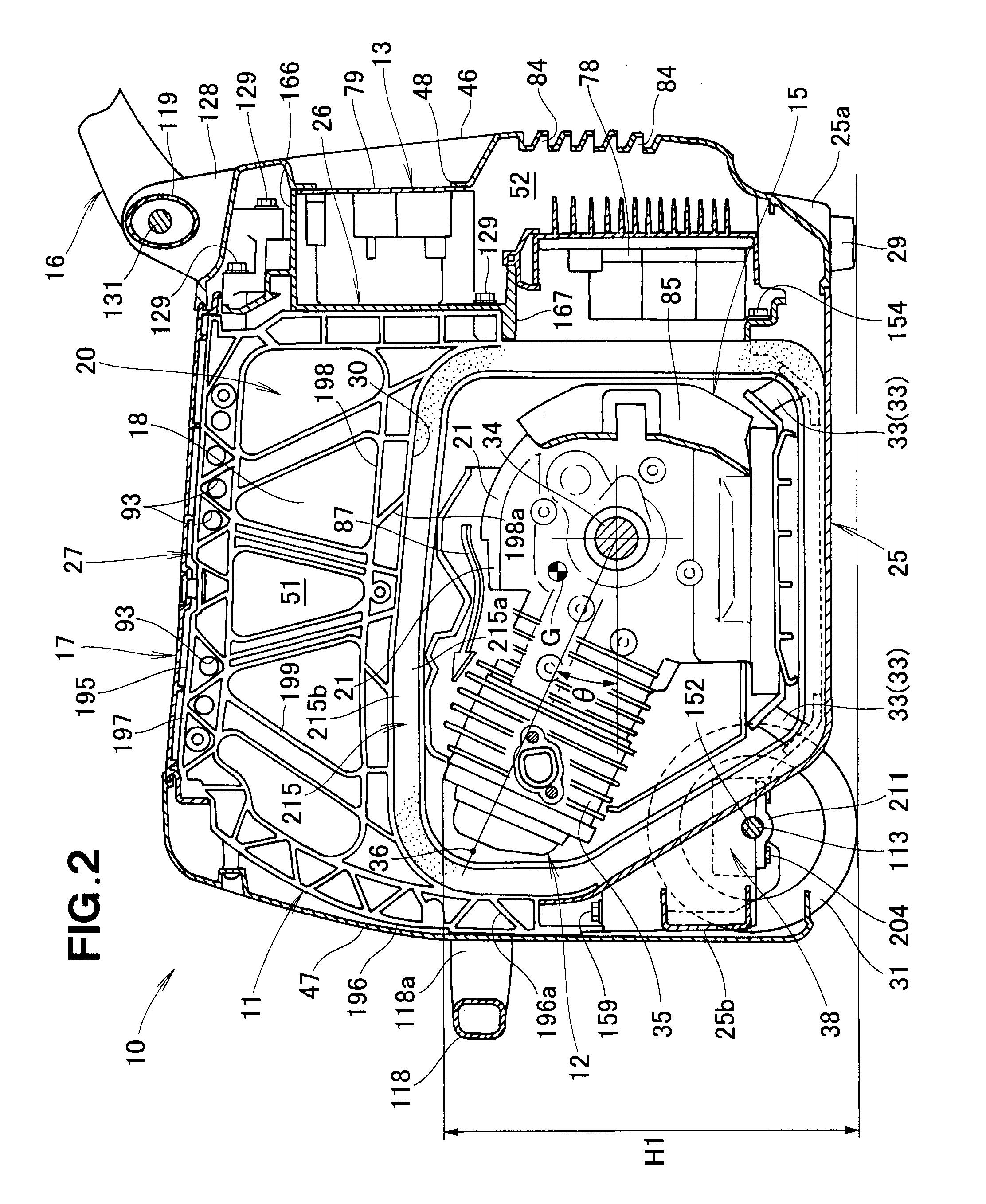
[0040]Throughout the description of the present embodiment, the term “forward direction” represents a direction in which an engine generator 10 is pulled by a draw handle 125.

[0041]The engine generator 10 shown in FIGS. 1 and 2 is provided with a skeletal member 11 that forms a main skeletal body, an engine / generator unit 12 provided to the skeletal member 11, and an electrical component section 13 for controlling the output of the engine / generator unit 12, an intake / fuel feed mechanism 14 (see FIG. 3) for feeding fuel to the engine / generator unit 12, a cooling structure 15 for directing cooling air to the engine / generator unit 12, a transport structure 16 for transporting the engine generator 10, a case 17 for covering the engine / generator unit 12 and the electrical component section 13, an insulating material 18 for partitioning accommodation space 20 inside the case 17, a muffler 23 (see FIG. 3) provided to an engine 21 of the engine / generator unit 12, and vibration suppressing m...


PUM


Abstract

An engine generator having a high-rigidity rigid skeletal member. A bottom cover supports the engine/generator unit. A wall-shaped vertical frame is disposed transversely of the engine generator in a front section of the bottom cover and rising from the bottom cover front section. A T-shaped center frame extends between a rear section of the bottom cover and the vertical frame. The skeletal member includes the bottom cover, the vertical frame and the center frame.

Description

FIELD OF THE INVENTION[0001]The present invention relates to an engine generator in which a generator driven by an engine is accommodated inside a case together with the engine.BACKGROUND OF THE INVENTION[0002]Japanese Laid-open Patent Publication No. 2005-133638 discloses an engine generator in which an engine and a generator are accommodated in a noise-reducing (muffling) case.[0003]The engine generator is provided with a skeletal section of the case formed by a reinforced frame having an inverted U-shape in cross-section erectly disposed on the two side sections of the bottom plate for supporting the engine and the generator. The skeletal section is covered by a resin case. The engine and the generator are accommodated inside the case and a grip for transporting the case is integrally provided to form a small engine generator.[0004]The small engine-driven generator has lower end sections of a pair of reinforcement frames having an inverted U-shape in cross section that are connec...

Claims


Application Information

Patent Timeline
Patent Type & Authority Applications(United States)
IPC IPC(8): F02B63/04
CPCF02B63/047F02B63/04F02B77/00F16F7/00
Inventor HIROSE, TADAFUMIHIRANUMA, JUNJISHIN, MASANORIYUKI, HITOSHIKAI, MASASHI
Owner HONDA MOTOR CO LTD
Why Eureka
Try Eureka