Permanent-magnet type electric rotating machine and permanent-magnet type electric rotating machine system for automobile or train

a technology of permanent magnet and rotating machine, which is applied in the direction of magnetic circuit rotating parts, magnetic circuit shape/form/construction, electric devices, etc., can solve the problems of stress and demagnetization, and achieve the effect of preventing heat demagnetization

Inactive Publication Date: 2009-12-31
HITACHI LTD
View PDF6 Cites 30 Cited by
  • Summary
  • Abstract
  • Description
  • Claims
  • Application Information

AI Technical Summary

Benefits of technology

[0007]According to the present invention, it becomes possible to prevent the heat demagnetization due to the eddy current, which is ...

Problems solved by technology

Moreover, the increase in the magnet eddy current causes the magnet to liberate heat, thereby giving rise to a problem of the demagnetization.
This problem requires the execut...

Method used


Image

  • Permanent-magnet type electric rotating machine and permanent-magnet type electric rotating machine system for automobile or train
  • Permanent-magnet type electric rotating machine and permanent-magnet type electric rotating machine system for automobile or train
  • Permanent-magnet type electric rotating machine and permanent-magnet type electric rotating machine system for automobile or train

Examples


1st embodiment

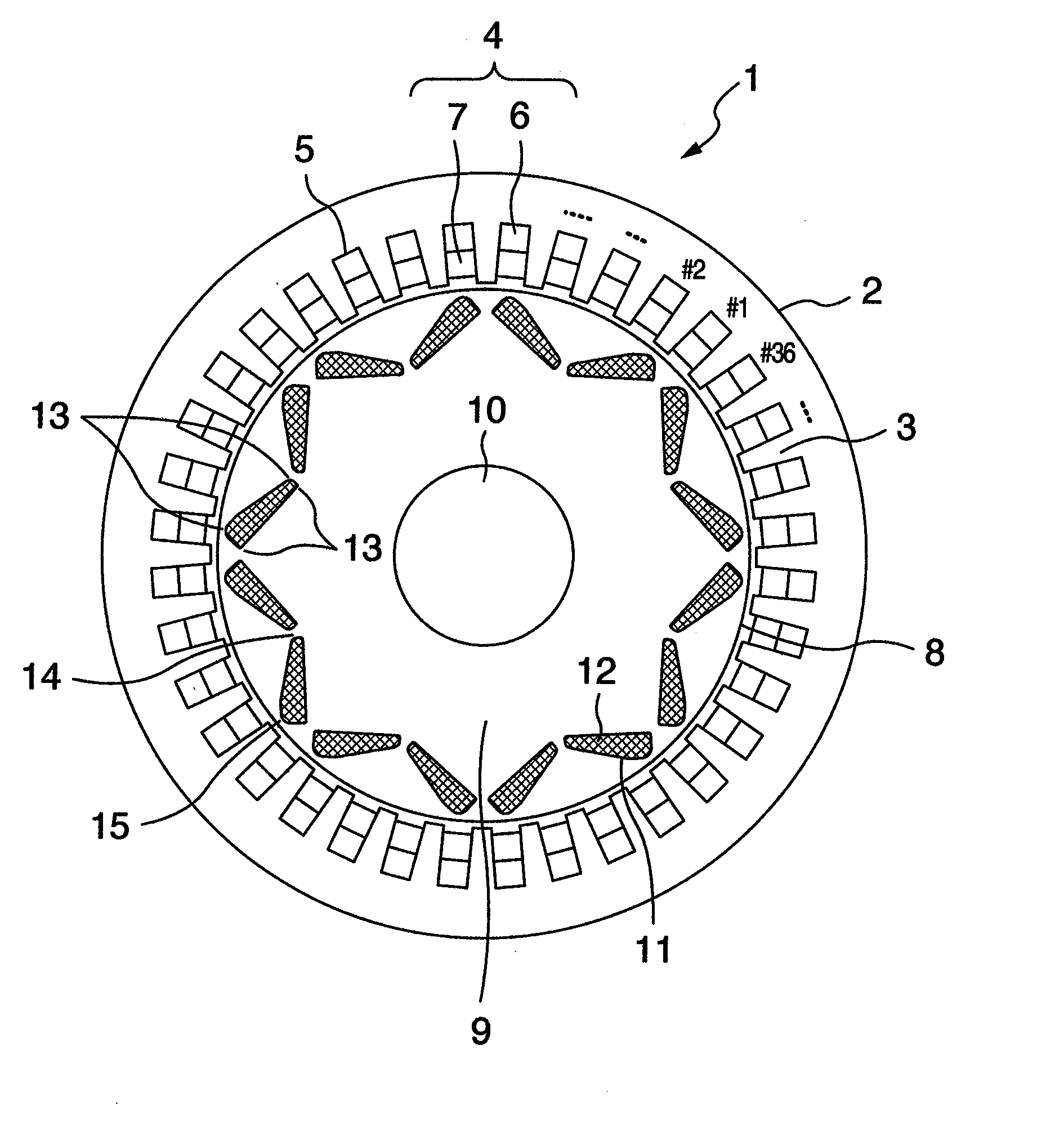
[0020]FIG. 1 is a cross-sectional diagram of the permanent-magnet type electric rotating machine, which becomes a first embodiment of the present invention. The permanent-magnet type electric rotating machine 1 is an 8-pole & 36-slot electric rotating machine. This 8-pole & 36-slot machine is used for a a-few-hundreds-of-kW-class train, and rotates in a range of 300 to 7000 min−1. A stator 2 is a distribution-winding stator, which includes a cylindrical stator iron-core equipped with a plurality of teeth 3 that protrude from a yoke portion onto its inner-circumference surface, and which also includes a coil 4 formed by winding an elemental wire in a distribution-like manner using the teeth 3. The coil 4 is configured by winding a 3-phase (i.e., U-phase, V-phase, and W-phase) winding so that the 8 poles are electrically implemented with the 36 slots. An upper coil 6 is deployed on the outer-diameter side of each slot 5 formed between the teeth 3, and a lower coil 7 is deployed on the...

2nd embodiment

[0025]FIG. 4 is a one-half edge-portion cross-sectional diagram of the rotor, which becomes a second embodiment of the present invention. A concave portion 16 is allowed to be provided in the outer circumference portion of the rotor iron-core 9, which becomes the center of the V-character pattern of the rotor 8, and which has been illustrated in the first embodiment. Providing the concave portion 16 makes it possible to reduce the weight of the iron-core which becomes the central portion of the V-character pattern, thereby allowing a reduction in the concentration stress concentrated onto the connection portion 14 which becomes the inner-diameter side of the rotor iron-core 9 of the V-character pattern's center. Moreover, an air layer is created in the portion in which the concave portion 16 has been provided. This air layer allows implementation of a reduction in the temperature transmitted to the permanent magnet 12. Also, a similar effect can be obtained by providing an empty hol...

3rd embodiment

[0026]FIG. 5 is a one-half edge-portion cross-sectional diagram of the rotor, which becomes a third embodiment of the present invention. The concave portion 16 is allowed to be provided in the inter-pole outer circumference in which polarities of the rotor 8 differ from each other, and which has been illustrated in the first and second embodiments. Providing the concave portion 16 creates an air layer. This air layer allows implementation of a reduction in the temperature transmitted to the permanent magnet 12.


PUM


Abstract

A rotor is deployed such that the rotor becomes coaxially rotatable with a stator. A shaft is fixed onto the axis of a rotor iron-core. 1-pole constituting magnet slots are deployed into V-character pattern along an outer circumference portion of the rotor iron-core. Permanent magnets are embedded into the magnet slots. For the 1 pole, the 2 pieces of same-polarity permanent magnets are embedded into the V-character pattern. The configuration of each embedded permanent magnet is designed as follows: From the thickness of the permanent-magnet edge portion on the inner-diameter side of the rotor iron-core, which becomes the center of the V-character pattern, the thickness of the permanent magnet gradually increases toward the outer-diameter side of the rotor iron-core, which become the right and left edge portions of the V-character pattern. Simultaneously, curved lines are provided on both edge portions of the permanent magnet.

Description

BACKGROUND OF THE INVENTION[0001]The present invention relates to a permanent-magnet type electric rotating machine, and an automobile-or-train-targeted permanent-magnet type electric rotating machine system including the same machine.[0002]Up to the present time, an induction motor has been employed as the electric rotating machine used for railroad vehicles. In recent years, however, there has been a growing trend to employ a permanent-magnet type electric rotating machine which allows its small-sized and light-weighted implementation and high-efficiency implementation. This growing trend has arisen from low-cost implementation of the permanent magnet and prevalence of the high-performance inverter.[0003]Under the circumstances like this, in order to improve electric characteristics and strength characteristics of the electric rotating machine, consideration is now being given to the permanent-magnet type rotor structure of various forms. In JP-A-9-90517, the following permanent-m...

Claims


Application Information

Patent Timeline
IPC IPC(8): H02K1/27
CPCH02K1/2766B60L3/0061B60L11/1803Y02T10/641B60L2240/36B60L2260/28Y02T10/7005B60L2200/26B60L50/51Y02T10/64Y02T10/70
Inventor KORI, DAISUKEKIMURA, MAMORUMIKAMI, HIROYUKIMASUDA, SEIKICHIFUJIEDA, MASAYASU
Owner HITACHI LTD
Why Eureka
Try Eureka