Traffic signals control system

a traffic signal and control system technology, applied in traffic control systems, analog computers, hybrid computing, etc., can solve the problems of not responding at all to unexpected real time changes, conventional traffic control systems cannot provide adequate use of controlled intersections, and usually a long average waiting time for vehicles, etc., to achieve the effect of maximizing the reward

Active Publication Date: 2009-12-31
ROADS AND MARITIME SERVICES
View PDF5 Cites 49 Cited by
  • Summary
  • Abstract
  • Description
  • Claims
  • Application Information

AI Technical Summary

Benefits of technology

[0013]According to a first aspect of the present invention, there is provided A method of controlling traffic signals at a road intersection which has a plurality of signal groups, each of which controls at least one direction of traffic within the intersection, the method comprising the steps of: obtaining and utilising traffic data to calculate a current traffic state and the rate of change in the traffic state; formulating at least one action and the duration of said action in response to the calculations obtained in step (i), wherein each action comprises switching at least one traffic signal; resolving one or more policies based on the calculations obtained in step (i) and the action formulated in step (ii); applying a continuous decision making process to evaluate a reward for the policies resolved in step (iii); and selecting a policy that maximizes the reward.

Problems solved by technology

These plans are fixed and do not respond at all to unexpected real time changes in traffic flow.
Conventional traffic control systems cannot provide adequate utilisation of controlled intersections.
As a result, there is usually a long average waiting time for vehicles to cross intersections that are controlled by conventional traffic control systems.
However, these adaptive phase systems are still not capable of adapting to unanticipated flow patterns.
None of the previously devised adaptive control systems can provide a greater degree of flexibility than controlling individual signal groups.
The known adaptive control systems demonstrate significant drawbacks when unplanned traffic flow conditions are encountered.
This is because these existing adaptive controllers are limited to switching between a limited number of phases in a predetermined order.
These techniques are sensitive to variations, and are unable to allow the system to respond quickly to high rates of traffic flow changes.

Method used


Image

  • Traffic signals control system
  • Traffic signals control system
  • Traffic signals control system

Examples


Embodiment Construction

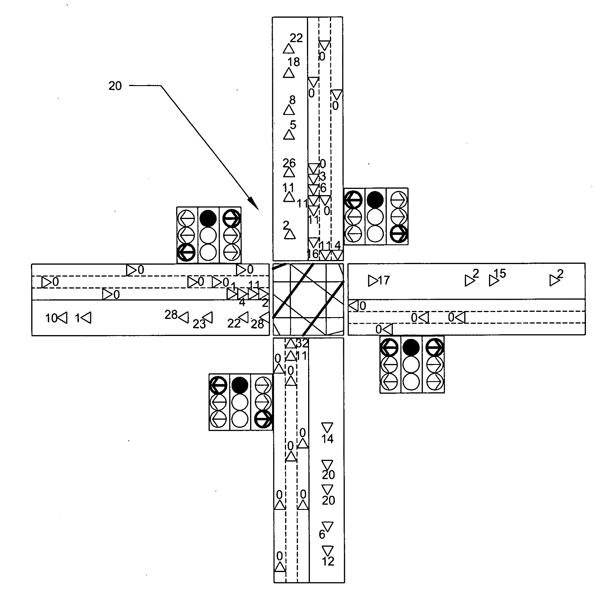
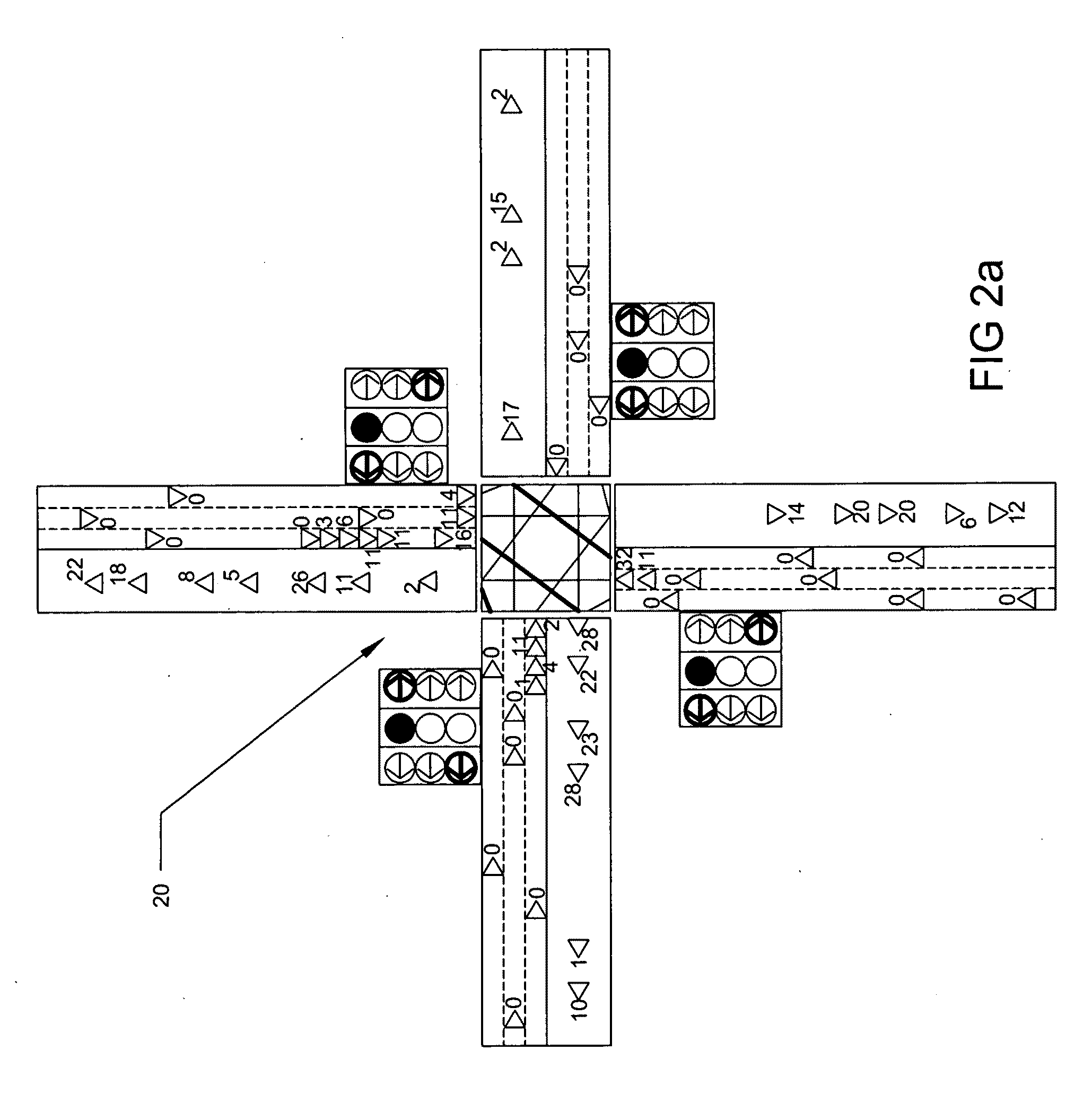
[0062]The present invention relates to a method and a system for controlling traffic lights at intersections. The present invention particularly relates to an intelligent traffic signals control system. The design of the traffic signals control system is based on an intelligent agent architecture, which can perceive its environment through sensors and act upon that environment through actuators.

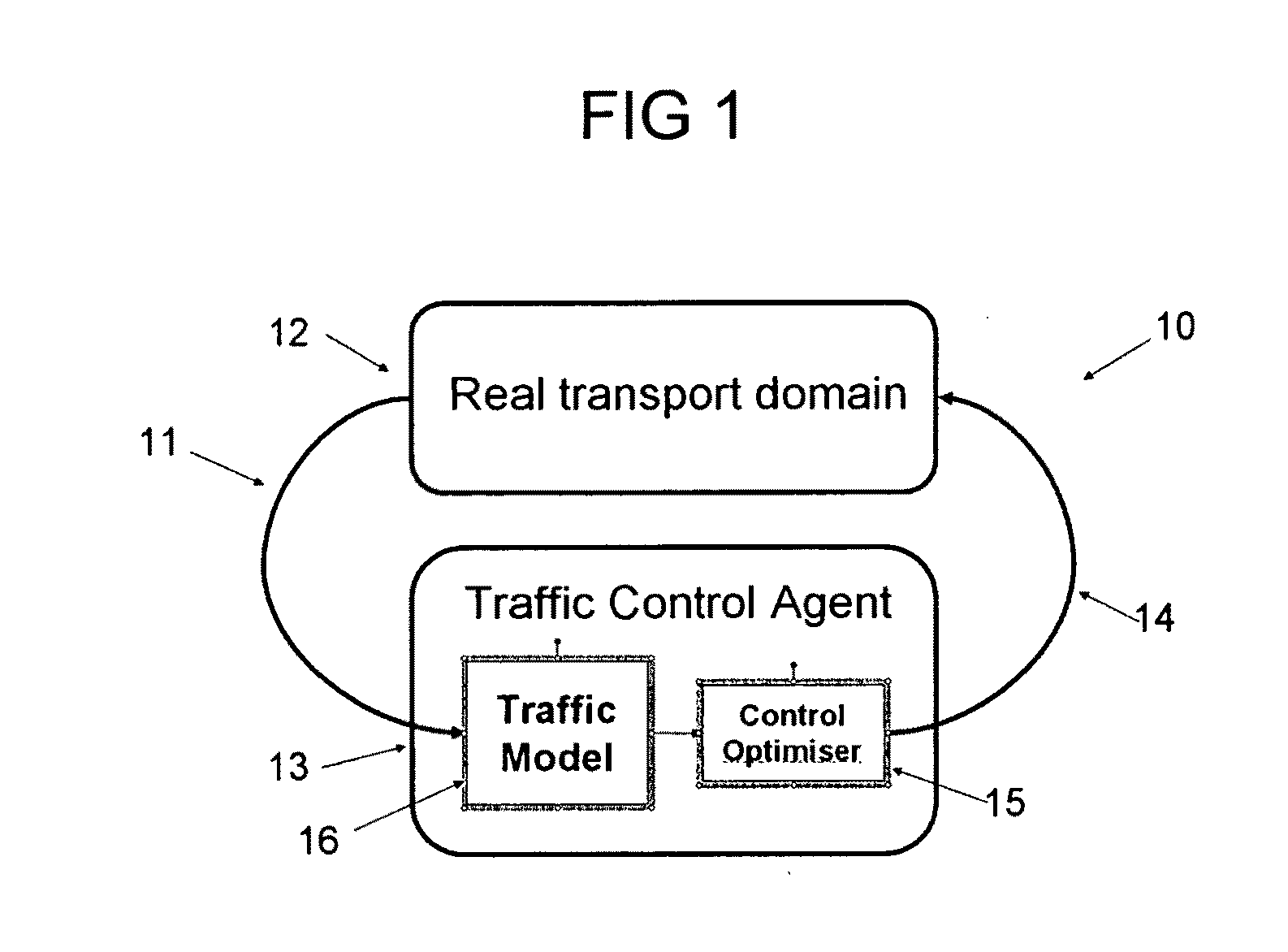
[0063]FIG. 1 shows a high level architecture of the traffic signals control system 10 (“TSCS”) according to a first embodiment of the present invention. The architecture is based on a sense-act agent model. The arrow 11 from the real transport domain 12 to the control agent 13 represents incoming sensor data and the other arrow 14 represents the actuator data. In the TSCS 10, sensors typically include loop detectors and video cameras, radar devices, infra-red sensors, radio frequency identification (RFID) tags or Global Positioning System (GPS) devices or any other suitable sensors, and the a...


PUM


Abstract

A method of controlling traffic signals at a road intersection, which has a plurality of signal groups, each of which controls at least one direction of traffic within the intersection. The method comprises the steps of obtaining and utilising traffic data to calculate a current traffic state and the rate of change in the traffic state. The method further comprises formulating at least one action and the duration of the action in response to these calculations. Each action comprises switching at least one traffic signal. One or more policies based on the calculations and the action are resolved. A continuous decision making process is applied to evaluate a reward for the policies resolved and a policy that maximizes the reward is selected.

Description

RELATED APPLICATIONS[0001]The present application claims priority benefit to Australian Patent Application No. 2008902826, filed Jun. 4, 2008, entitled “Traffic Signals Control System”, the entirety of which is hereby incorporated by reference.TECHNICAL FIELD[0002]The present invention relates to a method for controlling traffic lights at intersections.[0003]In particular, the present invention relates to a system and to a software platform for carrying out a method of controlling and switching of signal groups at intersections to optimise the flow of traffic based on utility functions. The signal groups comprise a set of lights such as red, green, yellow and off (no lights), that are always switched simultaneously. The method further includes the steps of detecting the point in time when a queue of vehicles at an intersection has fully discharged at traffic lights based on the signals from at least a single loop-detector located at the stop line. The method also estimates the avera...

Claims


Application Information

Patent Timeline
Patent Type & Authority Applications(United States)
IPC IPC(8): G08G1/095
CPCG08G1/08
Inventor MORIOKA, NOBUYUKIHUANG, ERIC ENYANGHENGST, BERNHARD
Owner ROADS AND MARITIME SERVICES
Why Eureka
Try Eureka